888. pr s. 4t ec, Fig. 4, Fig. 5 – Prescolite MC10LED CYLINDER - PENDANT MOUNT User Manual
Page 2: Fig. 3
Part No...........................................
With representatives offices in principal cities throughout North America.
Copyright , revision, All Rights Reserved - Printed in U.S.A.
701 Millennium Blvd • Greenville, SC 29607
www.pre
s
c
o
lit
e
.c
o
m
y
Pr
escolite T
o
ll F
ree T
e
chnical Support
1.
888.
PR
S.
4T
EC
y
H
our
s: 8am
- 5pm
ET
93053634
2014
02/24/14
ROTATE
FIXTURE
LEADS IN
WIRING
COMPARTMENT
Fig. 4
FIXTURE
LEADS
THREAD
CLAMP
SCREW
CANOPY
Fig. 5
SLIDE
HOUSING
CLOSED
PHILLIPS
SCREW
(1 OF 2)
LOCKING
SLOT
PENDANT
THREADS
KEEP THESE INSTALLATION INSTRUCTIONS!
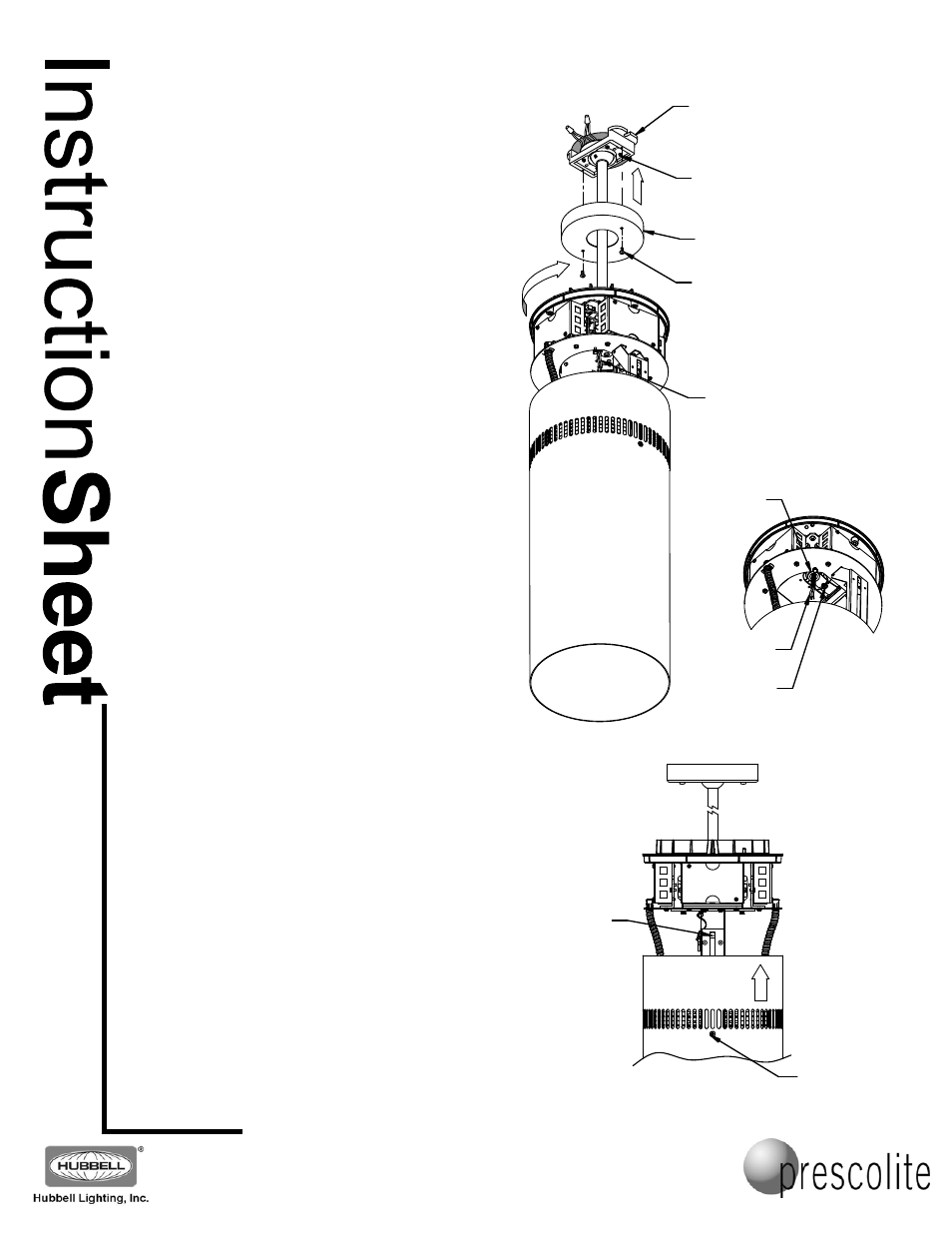
5. Carefully flip the cylinder upright and rest the pendant
canopy on the top of the fixture with its opening facing
up, (the way it will be mounted to the pendant mount
assembly later). Lift the cylinder assembly up to the
pendant threaded end, and feed the fixture leads
through the threaded hole in the center of the fixture
top assembly. Engage the pendant threads, and
rotate the assembly a few times, being sure that the
fixture rotates freely and is not cross-threading (Fig
3). Pull the fixture leads out though the wiring
compartment opening. Make sure they hang freely
(don’t rotate or twist), and thread the fixture onto the
pendant until the pendant threads are fully engaged.
Tighten the thread clamp screw to lock the fixture
assembly onto the pendant threads. (Fig. 4)
WARNING: Failure to tighten the thread clamp
screw to lock the fixture assembly onto the
pendant threads may allow the fixture to turn and
fall!
6. Make the electrical connections in the fixture wiring
compartment. The line voltage (Black) wire connects
to the two-position connector with the Red thermal
protector wire. The neutral (White) wire attaches to
the empty position on the connector with the White
wires. If provided, connect the Violet and Gray control
wires to an empty position on the respective
connectors with Violet and Gray wires.
CAUTION: When making these connections, be
careful that no stray strands of wire stick out of
the connectors that might cause electrical shorts!
7. After the electrical connections are completed,
replace the wiring compartment cover and tighten the
thumbscrews to complete the wiring of the fixture.
8. Once again loosen (do not remove) the two Phillips
screws on opposite sides of the cylinder until the
cylinder housing is free to slide. Slide MC10LED outer
cylinder housing upwards until it seats on the finned
casting.
CAUTION: Do not pinch any wires between the
cylinder housing and any other parts of the
fixture!
9. Be sure the cylinder housing is completely seated,
and tighten the two Phillips screws to lock the cylinder
housing in place.
Note: If the cylinder housing does not fully seat when
closing, you may need to loosen the screws a little
more to slide it closed. This will allow the ends of the
screws to pass the locking slots at the very end of the
slide travel (Fig. 5).
5. If the fixture is not hanging straight, loosen the four
ball clamp screws in the pendant casting. Align the
fixture and retighten the screws. After adjustment is
complete, install the canopy.
Note: If the fixture is installed in areas subject to heavy vibration or
earthquakes, a safety chain or cable is recommended (by others).
Fig. 3
PENDANT
MOUNT
ASSEMBLY
CANOPY
RETAINING
SCREWS
BALL
CLAMP
SCREWS