Instruction sheet, Prs.4tec – Prescolite FT6QLIC User Manual
Page 3
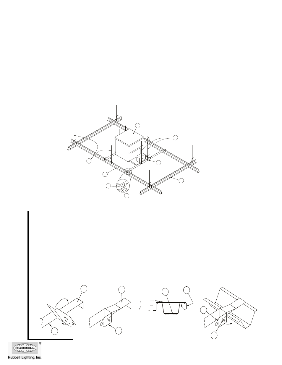
Installation Instructions for the Prescolite FtFCC Furring Channel Clips
(included) to be used in fire rated applications using Furring Channels
1. Attach one Furring Channel Bracket (36) to each Hanger Bar (37) as shown in Fig. 6 and 7. CAUTION: Maintain
a firm hold on Luminaire until Steps 2 and 3 are complete.
2. Lift Luminaire (30) to position Furring Channel Brackets over Furring Channels (38) and secure in place by bend-
ing Tabs (39) over as shown in Fig. 8.
3. Once all Brackets are in place bend Hanger Bar End (40) around to secure Brackets to the Channels as shown
in Figure 9. NOTE: Nailer Tab (41) should lodge under edge of Furring Channel.
4. Tighten bar hanger Locking Screws (5) in ends of Plaster Frame (2) to prevent lateral movement of the Frame.
5. Install two No. 12 SWG Galv. Steel Hanger Wires (34) secured to each end of Luminaire (30) plaster frame at
Lanced Openings (35) in hanger bar support channels. Steel Hanger Wires to be installed vertically and secured to
structural members of floor or roof assembly. (See Fig. 5)
6. See Steps 2 through 6 on Page 1 to complete installation.
www.prescolite.com
• Prescolite
TollFree
Technical
Support
1.888.PRS.4TEC
•
Hours:
8am
- 5pm
ET
701 Millennium Blvd., • Greenville, SC 29607
With representatives offices in principal cities throughout North America.
Copyright 2011, 8/2/11 revision, All Rights Reserved - Printed in U.S.A.
Instruction Sht. No.. . . . . . . . . . . . . . . . . . . . . . . . 93037150
INStAllAtION INStRuCtIONS FOR FIRE RAtED APPlICAtIONS uSING t-BA
R
1. Install No. 12 SWG Galv. Steel Hanger Wire (28) on Main Runners (29) at four corners of grid module containing
Luminaire (30). When Main Runners are spaced greater than 24 in. on center, Cross Tees (31) forming sides of
gridmodule containing Luminaire to be supported by Steel Hanger Wire at Cross Tee midspan.
2. Place the Luminaire (30) on the ceiling grid with the “T” Bars running through the Hanger Bar Notches (32). Fold
the Hanger Bar ends closed to engage the integral Tabs (33). Secure with pliers if necessary.
3. Install two No. 12 SWG Galv. Steel Hanger Wires (34) secured to each end of Luminaire (30) plaster frame at
Lanced Openings (35) in hanger bar support channels. Steel Hanger Wires to be installed vertically and secured
to structural members of floor or roof assembly.
4. Tighten bar hanger Locking Screws (5) in ends of Plaster Frame (2) to prevent lateral movement of the Frame.
5. See Steps 2 through 6 on Page 1 to complete installation.
Instruction
Sheet
Fig. 5
35
34
33
32
31
30
29
28
Fig. 9
Fig. 8
Fig.6
Fig. 7
2
1
38
41
40
39
37
36
37
36