B. errors – Pololu Maestro User Manual
Page 24
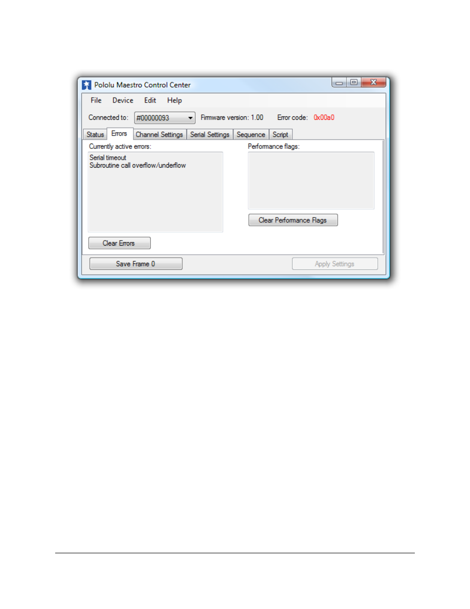
4.b. Errors
The Errors tab in the Maestro Control Center.
The Errors tab indicates problems that the Maestro has detected while running, either communications errors or errors
generated by bugs in a script.
Each error corresponds to a bit in the two-byte error register. The red LED will be on as long as any of the bits in the
error register are set to 1 (it can also be turned on by the led_on script command). The value of the error register is
displayed in the upper right corner of the main window.
When an error occurs, the corresponding bit in the error register is set to 1 and the Maestro sends all of its servos and
digital outputs to their home positions, as specified in the Settings tab (
). Any servos or outputs that are
configured to be in the “Ignore” mode will not be changed. The error register is cleared by the “Get Errors” serial
command.
The errors and their corresponding bit numbers are listed below:
• Serial Signal Error (bit 0)
A hardware-level error that occurs when a byte’s stop bit is not detected at the expected place. This can occur if
you are communicating at a baud rate that differs from the Maestro’s baud rate.
• Serial Overrun Error (bit 1)
A hardware-level error that occurs when the UART’s internal buffer fills up. This should not occur during normal
operation.
• Serial RX buffer full (bit 2)
A firmware-level error that occurs when the firmware’s buffer for bytes received on the RX line is full and a byte
from RX has been lost as a result. This error should not occur during normal operation.
Pololu Maestro Servo Controller User's Guide
© 2001–2014 Pololu Corporation
4. Using the Maestro Control Center
Page 24 of 73