B. supported microcontrollers – Pololu USB AVR User Manual
Page 5
The GND line provides direct access to the grounded line on the USB cable (and ground on the programmer).
The TX and RX lines are the TTL serial port for the USB-to-TTL-serial adapter. They are labeled from the computer’s
perspective: TX is an output that connects to your target’s serial receive pin and RX is an input that connects to your
target’s serial transmit pin.
describes how to use these lines to communicate with your devices from the
computer.
The A and B lines can be used as serial control/handshaking lines for the USB-to-TTL-serial adapter (see
) or as analog voltage inputs for the SLO-scope (see
).
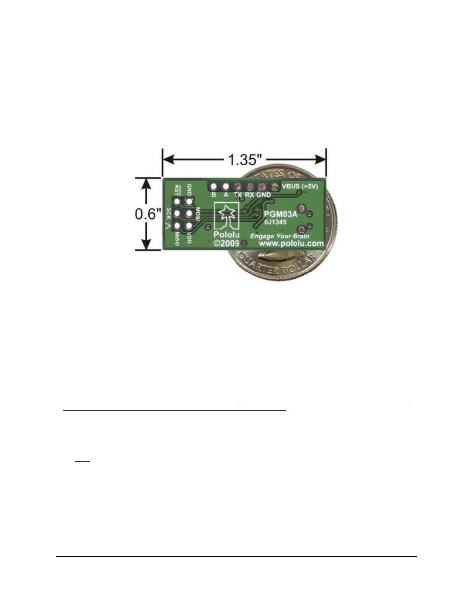
Pololu USB AVR programmer bottom view with
dimensions.
The USB AVR programmer has a standard 6-pin AVR ISP connector for programming AVRs, and the pins are
labeled on the silkscreen on the bottom side of the board. The pins on the connector are:
1. MISO: The “Master Input, Slave Output” line for SPI communication with the target AVR. The programmer
is the master, so this line is an input.
2. VDD: An input line that the programmer uses to measure the voltage of the target AVR. While programming
the target device, the programmer uses this line to constantly monitor the target VDD. If the voltage goes
too low or varies too much, then the programmer aborts programming in order to avoid damage to the target
AVR.
has more information about target VDD monitoring. The VDD line is not used to power the
programmer; the programmer is powered from the USB. This line cannot be used to power the target device; the
target device must be independently powered for programming to work.
3. SCK: The clock line for SPI communication with the target AVR. The programmer is the master, so this line
is an output during programming.
4. MOSI: The “Master Output, Slave Input” line for SPI communication with the target AVR. The programmer
is the master, so this line is an output during programming.
5. RST: The target AVR’s reset line. This line is used as an output driven low during programming to hold the
AVR in reset.
6. GND: Ground. This line should be connected to the target device’s ground.
1.b. Supported Microcontrollers
The programmer should work with all AVRs that can be programmed with the AVR ISP interface, but it has not
been tested on all devices. It has been tested with all Orangutan
Pololu USB AVR Programmer User's Guide
© 2001–2014 Pololu Corporation
1. Overview
Page 5 of 54