Pololu USB AVR User Manual
Page 44
input or an output by identifying it with a serial handshaking line. The table below shows which handshaking lines
are available (CTS is not available because there is no provision for it in the USB CDC ACM subclass).
Direction Name .NET System.IO.Ports.SerialPort member
Output
DTR
DtrEnable
Output
RTS
RtsEnable
Input
CD
CDHolding
Input
DSR
DsrHolding
Input
RI
N/A
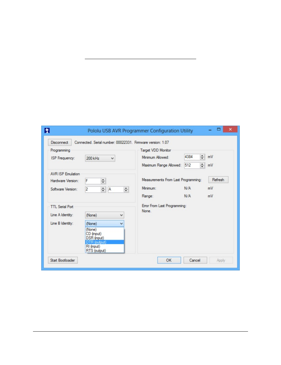
By default, pins A and B are high-impedance inputs that are not identified with any handshaking line. To use
pins A and/or B, you must configure them to be serial handshaking lines using the Pololu USB AVR Programmer
Configuration Utility (see
). The programmer stores the configuration in persistent memory.
Pins A and B can be identified with serial handshaking lines using the Pololu USB AVR
Programmer Configuration Utility.
After your have associated pins A and/or B with serial handshaking lines, you can take advantage of the I/O
capabilities of A and B. For input lines, this means you can get a digital reading of the voltage on the line over USB.
For output lines, this means you can set the voltage on the line over USB. A voltage of 0 V corresponds to a logical
1, while a voltage of 1 V corresponds to a logical 0.
Pololu USB AVR Programmer User's Guide
© 2001–2014 Pololu Corporation
6. Communicating via the USB-to-TTL-Serial Adapter
Page 44 of 54