Measuring voltages using the slo-scope, Section 7 – Pololu USB AVR User Manual
Page 46
7. Measuring Voltages Using the SLO-scope
A second bonus feature of the Pololu USB AVR programmer is the severely limited oscilloscope (SLO-scope), which
uses lines A and B as inputs to measure TTL-level voltages at a sample rate of up to 20 kHz. The SLO-scope has two
operating modes:
• Two 8-bit analog channels sampling at 10 kHz
• One 7-bit analog channel (A) and one digital channel (B) sampling at 20 kHz
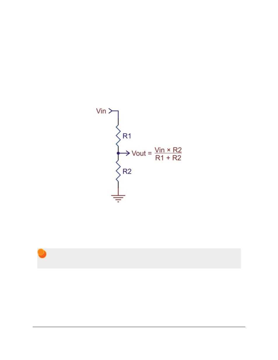
The SLO-scope can measure voltages between ground and approximately 5 V (depending on your computer’s USB
bus voltage); you can measure higher voltages by passing them through an external voltage divider before connecting
them to the programmer. The following schematic shows a general voltage divider circuit that can be used to scale
down an input signal to the SLO-scope’s required 0 – 5 V range:
The total resistance of R1+R2 should be as large as possible to minimize the divider’s effect on your signal, but it
should not exceed 100 kΩ or so.
Installing and Runing the Pololu SLO-scope Application
The SLO-scope application for Windows comes with the Windows drivers (
) and can be installed by
running the installation batch file sloscope_installer.bat.
Windows Vista: right click on sloscope_installer.bat and select “Run as administrator”.
Windows XP: simply double click on sloscope_installer.bat.
At this time, the SLO-scope can only be used under the Windows operating system. Once installation is complete, the
application should begin running automatically. Note that the application will give you an error message and close if
a programmer is not connected to your computer. To start the SLO-scope application yourself, open the Start menu
and navigate to:
All Programs > Pololu > SLO-scope
Pololu USB AVR Programmer User's Guide
© 2001–2014 Pololu Corporation
7. Measuring Voltages Using the SLO-scope
Page 46 of 54