Pegasus user’s guide – Orbital Pegasus User Manual
Page 68
Release 7.0
Apr 2010
57
Pegasus User’s Guide
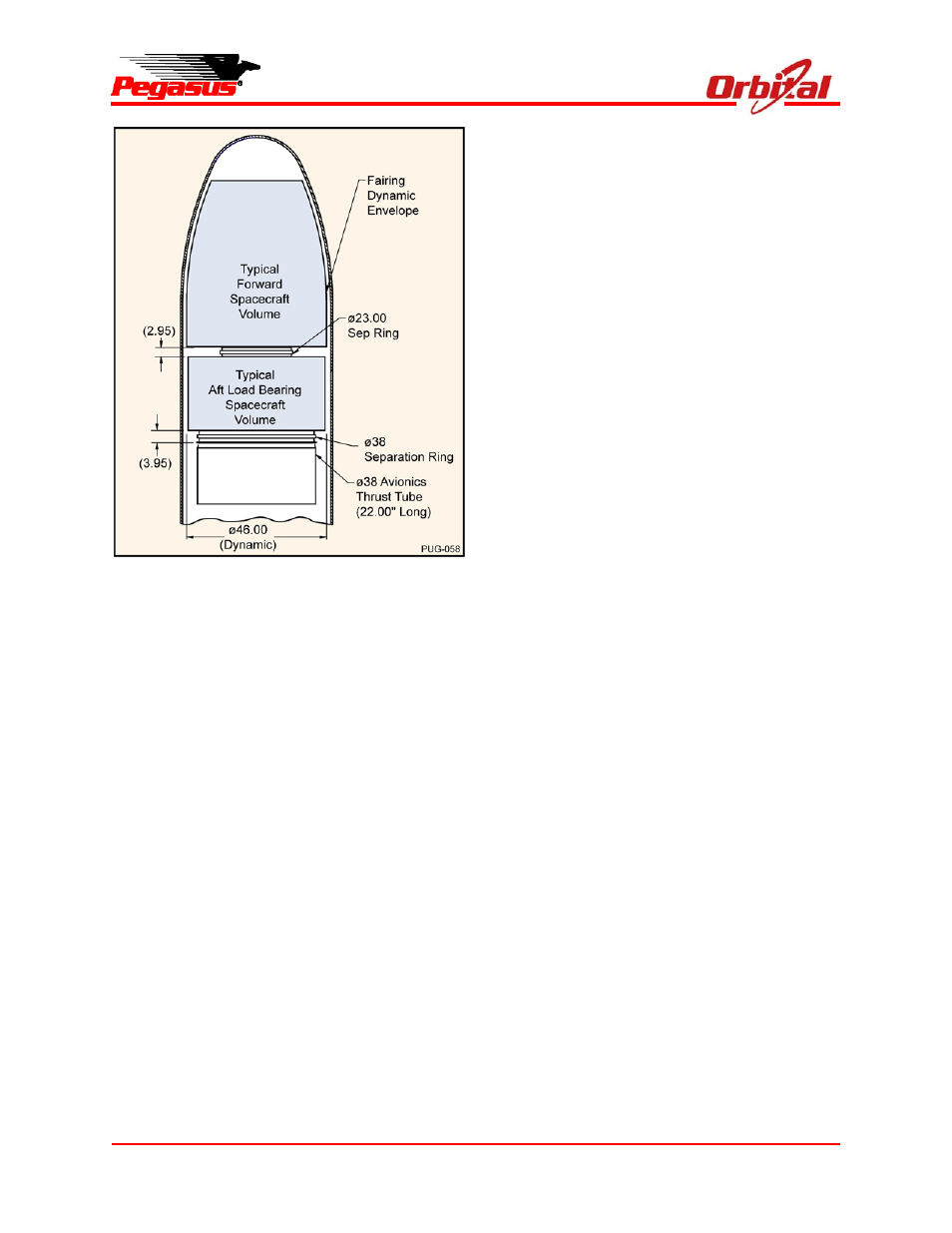
Figure 9-1. Load-Bearing Spacecraft
Configuration
Two approaches may be taken for load-bearing
spacecraft. The first approach involves the use of
an Orbital design using the MicroStar bus,
successfully developed and flown for ORBCOMM
spacecraft. The MicroStar bus features a circular
design with an innovative, low-shock separation
system. The spacecraft bus is designed to allow
stacking of co-manifested payloads in “slices”
within the fairing. The bus design is compact and
provides exceptional lateral stiffness.
The second approach is to use a design
developed by other spacecraft suppliers, which
must satisfy Pegasus and forward payload
structural design criteria. The principal
requirements levied load-bearing spacecraft are
those involving mechanical and electrical
compatibility with the forward payload. Structural
loads from the forward payload during all flight
events must be transmitted through the aft
payload to the Pegasus. Orbital will provide
minimum structural interface design criteria for
shear, bending moment, axial and lateral loads,
and stiffness.
For preliminary design purposes, coupled effects
with the forward payload can be considered as a
rigid body design case with Orbital-provided mass
and c.g parameters. Integrated CLA will be
performed with test verified math models provided
by the payload contractors. These analyses are
required to verify the fundamental frequency and
deflections of the stack for compliance with the
Pegasus requirement of 20 Hz minimum. Design
criteria provided by Orbital will include “stack”
margins to minimize interactive effects associated
with potential design changes of each payload.
Orbital will provide the necessary engineering
coordination between the spacecraft and launch
vehicle.
Electrical pass-through harnesses will also need to
be provided by the aft payload along with
provisions for connectors and interface
verification. The spacecraft supplier will need to
provide details of the appropriate analyses and
tests to Orbital to verify adequacy of margins and
show that there is no impact to the forward
spacecraft or the launch vehicle.
9.2. Non-Load-Bearing Spacecraft
For aft spacecraft that are not designed for
withstanding and transmitting structural loads from
the forward payload, the flight-proven Dual
Payload Attach Fitting (DPAF) is available on an
optional basis.
The DPAF structure (Figure 9-2) is an all graphite
structure that provides independent load paths for
each satellite. The worst-case “design payload”
for the DPAF is a 193 kg (425 lbm) spacecraft with
51 cm (20
in.) c.m. offset and first lateral
frequency of 20 Hz. The DPAF is designed to
accommodate this “design payload” at both the
forward and aft locations, although the combined
mass of the two payloads cannot exceed Pegasus
capabilities. The upper spacecraft loads are