Pegasus user’s guide – Orbital Pegasus User Manual
Page 17
Release 7.0
Apr 2010
6
Pegasus User’s Guide
developed for the Space Shuttle ascent guidance.
Attitude control is closed-loop.
The vehicle attitude is controlled by the Fin
Actuator System (FAS) during Stage 1 flight. This
consists of electrically actuated fins located at the
aft end of Stage 1. For Stage 2 and Stage 3 flight,
a combination of electrically activated Thrust
Vector Controllers (TVCs) on the Stage 2 and
Stage 3 solid motor nozzles and a GN2 Reaction
Control System (RCS) located on the avionics
section, control the vehicle attitude.
Figure 2-5 summarizes the attitude and guidance
modes during a typical flight, although the exact
sequence is controlled by the Mission Data Load
(MDL) software and depends on mission-specific
requirements.
2.1.6. Telemetry Subsystem
The Pegasus XL telemetry system provides real-
time health and status data of the vehicle avionics
system, as well as key information regarding the
position, performance, and environment of the
Pegasus XL vehicle. This data is used by Orbital
and the range safety personnel to evaluate system
performance.
Pegasus contains two separate telemetry
systems. The first provides digital data through
telemetry multiplexers (MUXs), which gather data
from each sensor, digitize it, then relay the
information to the flight computer. This Pegasus
telemetry stream provides data during ground
processing, checkout, captive carry, and during
launch. During captive carry, Pegasus telemetry
is downlinked to the ground and recorded onboard
the OCA. Some payload telemetry data can be
interleaved with Pegasus data as a nonstandard
service. The second system provides analog
environments data, which are transmitted via a
wideband data link and recorded for post-flight
evaluation.
2.1.7. Major Structural Subsystems
2.1.7.1. Wing
The Pegasus wing uses a truncated delta platform
with a double wedge profile. Wing panels are
made of a graphite-faced foam sandwich.
Channel section graphite spars carry the primary
bending loads and half-ribs, and reinforcing lay-
ups further stabilize the panels and reduce stress
concentrations. The wing central box structure
has fittings at each corner that provide the
structural interface between the Pegasus and the
OCA.
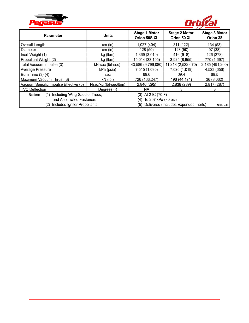
Figure 2-4. Typical Pegasus XL Motor Characteristics in Metric (English) Units