Pegasus user’s guide – Orbital Pegasus User Manual
Page 48
Release 7.0
Apr 2010
37
Pegasus User’s Guide
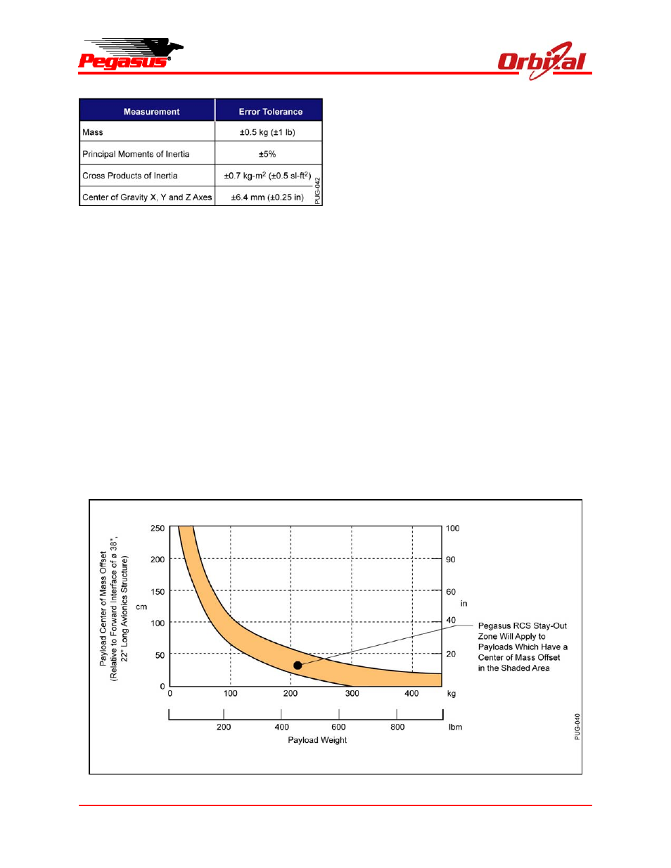
Figure 5-12. Payload Mass Property
Measurement Error Tolerances
receivers on the Pegasus launch vehicle. Prior to
launch, Orbital requires review of the payload
radiated emission levels (MIL-STD-461, RE02) to
verify launch vehicle EMI safety margins in
accordance with MIL-E-6051. Payload RF
transmissions are not permitted after fairing mate
and prior to separation of the payload. An
EMI/EMC analysis may be required to ensure RF
compatibility.
Payload RF transmission frequencies must be
coordinated with Orbital and range officials to
ensure noninterference with Pegasus and range
transmissions. Additionally, the customer must
schedule all RF tests at the integration site with
Orbital to obtain proper range clearances and
protection.
5.4.4. Payload Stiffness
In order to avoid dynamic coupling of the payload
modes with the 8-9 Hz natural frequency of the
Pegasus XL vehicle, the spacecraft should be
designed with a structural stiffness to ensure that
the fundamental frequency of the spacecraft, fixed
at the spacecraft interface, in the Pegasus Z axis
is greater than 20 Hz.
5.4.5. Payload Propellant Slosh
A slosh model should be provided to Orbital in
either the pendulum or spring-mass format. Data
on first sloshing mode are required and data on
higher order modes are desirable.
5.4.6. Customer Separation System Shock
Constraints
If the payload employs a non-Orbital separation
system, then the shock delivered to the Pegasus
Stage 3 vehicle interface must not exceed the limit
level characterized in Figure 4-3. Shock above
this level could require a requalification of units or
an acceptance of risk by the payload customer.
Figure 5-13. Detailed RCS Dead Band Zone