Pegasus user’s guide – Orbital Pegasus User Manual
Page 14
Release 7.0
Apr 2010
3
Pegasus User’s Guide
range coordination, launch site processing, and
operations. The mission team is responsible for
ensuring all mission requirements have been
satisfied.
2. PEGASUS DESCRIPTION
The Pegasus User’s Guide is dedicated to the
discussion of the Pegasus XL configuration,
capabilities, and associated services.
2.1. Pegasus XL Vehicle Description
Pegasus XL is a winged, three-stage, solid rocket
booster that weighs approximately 23,130 kg
(51,000 lbm), and measures 16.9 m (55.4 ft) in
length and 1.27 m (50 in.) in diameter, and has a
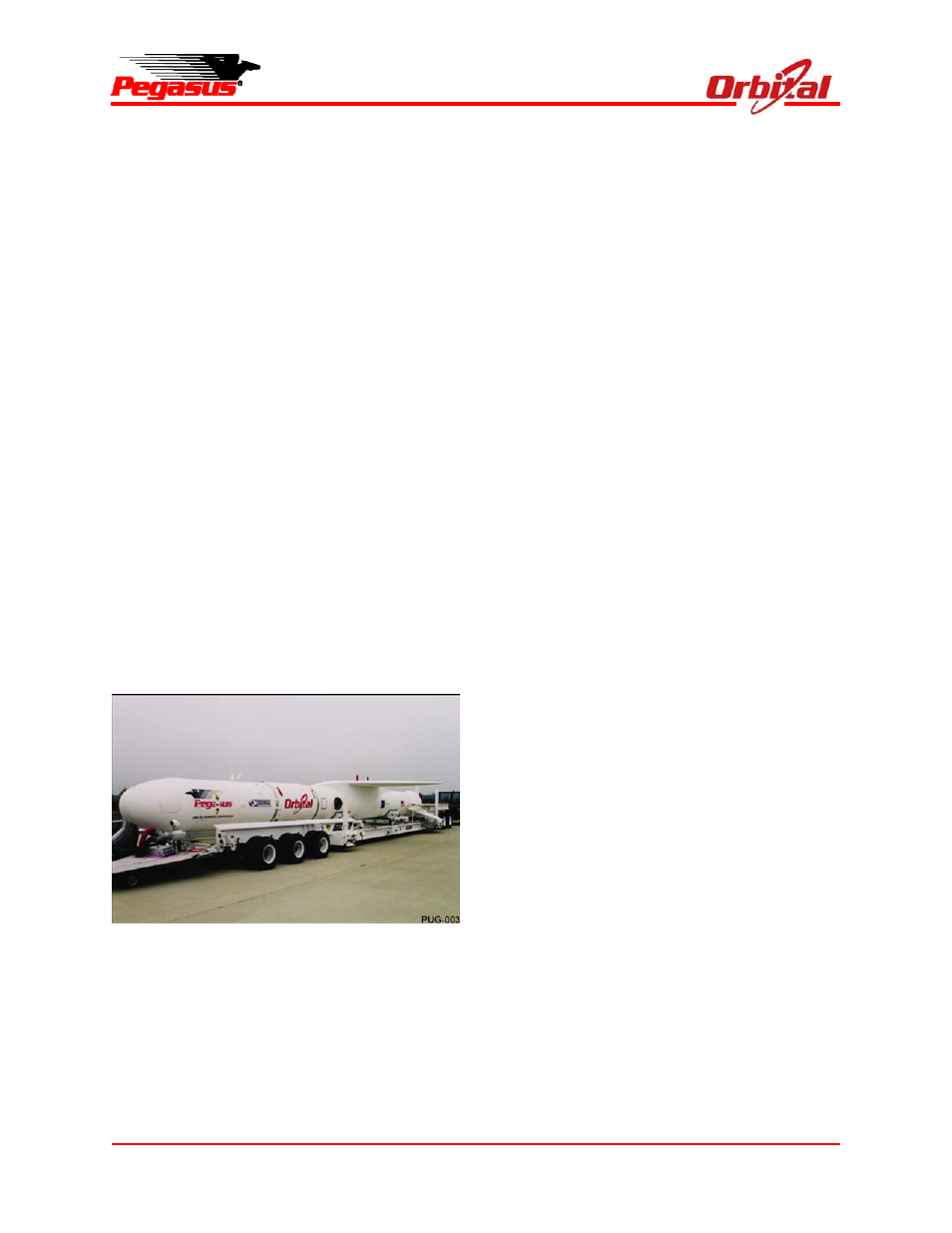
wing span of 6.7 m (22 ft). Figure 2-1 shows the
Pegasus on the Assembly Integration Trailer (AIT).
Pegasus is lifted by the OCA to a level flight
condition of about 11,900 m (39,000 ft) and Mach
0.82. Five seconds after release from the OCA
Stage 1 motor ignition occurs. The vehicle’s
autonomous guidance and flight control system
provide the guidance necessary to insert payloads
into a wide range of orbits.
Figure 2-1. Pegasus XL on the Assembly and
Integration Trailer (AIT)
Figure 2-2 shows an expanded view of the
Pegasus XL configuration. The Pegasus Vehicle
design combines flight-proven technologies, and
conservative design margins to achieve
performance and reliability. The vehicle
incorporates eight major elements:
Three solid rocket motors;
A payload fairing;
An avionics assembly;
A lifting wing;
Aft skirt assembly including three movable
control fins; and
A payload interface system.
Pegasus also has an option for a liquid propellant
fourth stage, HAPS (see Section 10). Figure 2-3
illustrates Pegasus XL’s principle dimensions.
2.1.1. Solid Rocket Motors
The three solid rocket motors were designed and
optimized specifically for Pegasus and include
features that emphasize reliability and
manufacturability. The design was developed
using previously flight-proven and qualified
materials and components. Common design
features, materials, and production techniques are
applied to all three motors to maximize cost
efficiency and reliability. These motors are fully
flight-qualified. Typical motor characteristics are
shown in Figure 2-4.
2.1.2. Payload Fairing
The Pegasus payload fairing consists of two
composite shell halves, a nose cap integral to a
shell half, and a separation system. Each shell
half is composed of a cylinder and ogive sections.
The two halves are held together with a base
frangible joint, two titanium straps along the
cylinder and a retention bolt in the nose. A cork
and Room Temperature Vulcanizing (RTV)
Thermal Protection System (TPS) provides
protection to the graphite composite fairing
structure. The amount of TPS applied has been
determined to optimize fairing performance and
payload environmental protection.
The two straps are tensioned using bolts, which
are severed during fairing separation with
pyrotechnic bolt cutters, while the retention bolt in
the nose is released with a pyrotechnic separation
nut. The base of the fairing is separated with