Pegasus user’s guide – Orbital Pegasus User Manual
Page 15
Release 7.0
Apr 2010
4
Pegasus User’s Guide
Orbital’s low-contamination frangible separation
joint. These ordnance events are sequenced for
proper separation dynamics. A hot gas generator
internal to the fairing is also activated at
separation to pressurize two piston-driven pushoff
thrusters. These units, in conjunction with cams,
force the two fairing halves apart. The halves
rotate about fall-away hinges, which guide them
away from the satellite and launch vehicle.
The fairing and separation system were fully
qualified through a series of structural, functional,
and contamination ground vacuum tests and have
been successfully flown on all Pegasus XL
missions. Section 5 presents a more detailed
description of the fairing separation sequence and
the satellite dynamic envelope.
2.1.3. Avionics
The Pegasus avionics system is a digital
distributed processor design that implements
developments in hardware, software, communi-
cations, and systems design. Mission reliability is
achieved by the use of simple designs, high
reliability components, high design margins, and
extensive testing at the component, subsystem,
and system level.
The heart of the Pegasus avionics system is a
multiprocessor, 32-bit flight computer. The flight
computer communicates with the Inertial
Measurement Unit (IMU), the launch panel
electronics on the carrier aircraft, and all vehicle
subsystems using standard RS-422 digital serial
data links. Most avionics on the vehicle feature
integral microprocessors to perform local
processing and to handle communications with the
flight computer. This RS-422 architecture is
central to Pegasus rapid integration and test, as it
allows unit and system-level testing to be
accomplished using commercially available
ground support equipment with off-the-shelf
hardware.
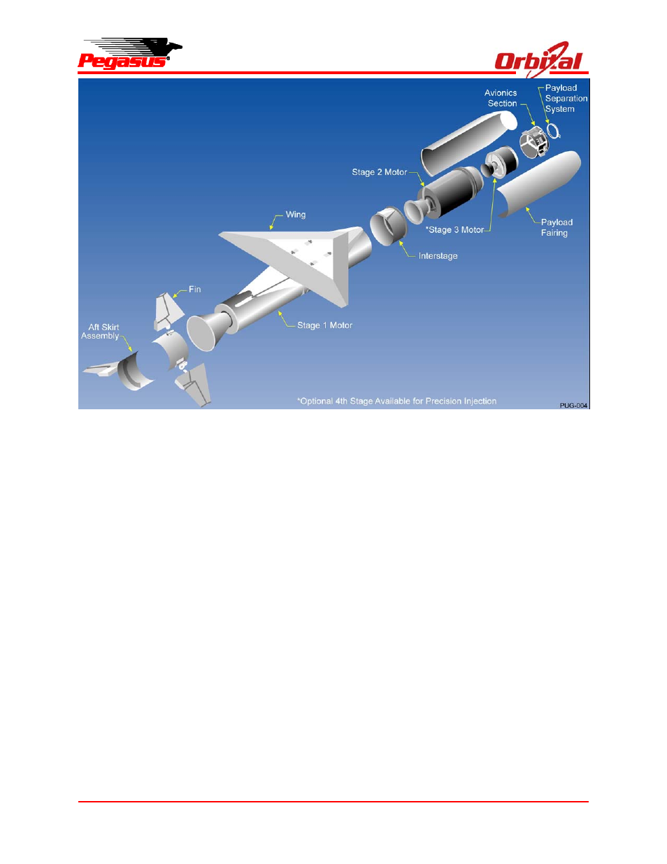
Figure 2-2. Expanded View of Pegasus XL Configuration