Pegasus user’s guide – Orbital Pegasus User Manual
Page 47
Release 7.0
Apr 2010
36
Pegasus User’s Guide
5.4. Payload Design Constraints
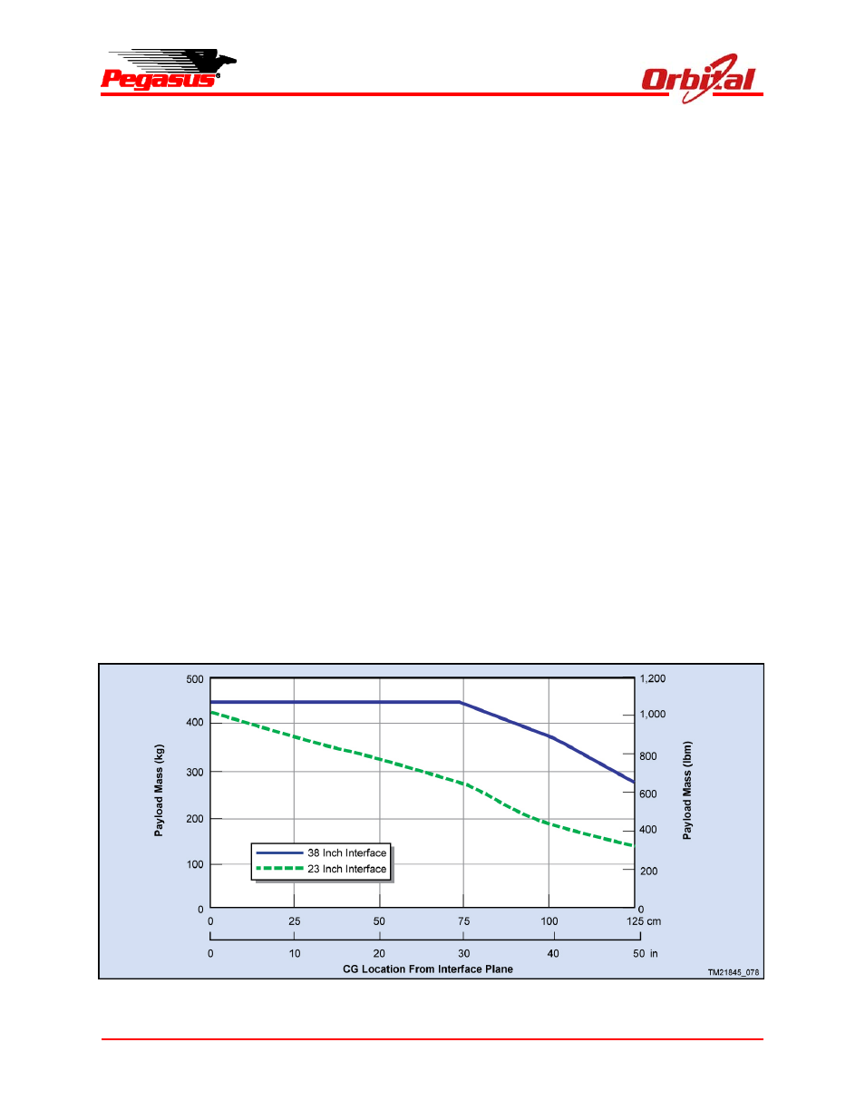
5.4.1. Payload Center of Mass Constraints
To satisfy structural constraints on the standard
Stage 3 avionics structure, the axial location of the
payload center of gravity (c.g.) along the X axis is
restricted as shown in Figure 5-11. Along the Y
and Z axes, the payload c.g. must be within 3.8
cm (1.5 in.) of the vehicle centerline for the
standard configuration and within 2.5 cm (1.0 in.)
of centerline if HAPS is used (including tolerances
in Figure 5-12). Payloads whose c.g. extend
beyond these lateral offset limits will require
Orbital to verify that structural and dynamic
limitations will not be exceeded. Payloads whose
X-axis c.g. falls into the RCS Dead Band Zone
referred to in Figure 5-13 will require movement of
the RCS thrusters, which can be supported on a
mission-specific basis.
Mass property measurements must adhere to the
tolerances set forth in Figure 5-12. The payload
center of mass (c.m.) must not transition through
the RCS Dead Band Zone during the unpowered
flight (before stage ignition or after burnout), or
loss of attitude control capability will occur.
5.4.2. Final Mass Properties Accuracy
The final mass properties statement shall specify
payload weight to an accuracy of 0.5 kg, the c.g.
to an accuracy to 6.4 mm in each axis, and the
products of inertia to 0.7 kg-m2. In addition, if the
payload uses liquid propellant, the slosh frequency
must be provided to an accuracy of 0.2 Hz, along
with a summary of the method used to determine
slosh frequency.
5.4.3. Payload EMI/EMC Constraints
The Pegasus avionics shares the payload area
inside the fairing such that radiated emissions
compatibility is paramount. The Pegasus avionics
RF susceptibility levels have been characterized
by test. During the mission integration process,
Orbital will provide specific notches that the
payload should incorporate into radiated emission
testing per MIL-STD-461 RE02. These notches
are intended to ensure that the payload does not
interfere with the S-band, C-band and GPS
Figure 5-11. Payload Mass vs. c.g. Location on X Axis