Pegasus user’s guide – Orbital Pegasus User Manual
Page 18
Release 7.0
Apr 2010
7
Pegasus User’s Guide
2.1.7.2. Aft Skirt Assembly
The aft skirt assembly is composed of the aft skirt,
three fins, and the fin actuator subsystem. The aft
skirt is an all-aluminum structure of conventional
ring and stressed-skin design with machined
bridge fittings for installation of the
electromechanical fin actuators. The skirt is
segmented to allow installation around the first
stage nozzle. Fin construction is a one-piece solid
foam core and wet-laid graphite composite
construction around a central titanium shaft.
2.1.7.3. Payload Interface Systems
Multiple mechanical and electrical interface
systems currently exist to accommodate a variety
of spacecraft designs. Section 5.0 describes
these interface systems. To ensure optimization
of spacecraft requirements, payload specific
mechanical and electrical interface systems can
be provided to the payload customer. Payload
mechanical fit checks and electrical interface
testing with these spacecraft unique interface
systems are encouraged to ensure all spacecraft
requirements are satisfied early in the processing
flow.
2.2. Orbital Carrier Aircraft
Orbital furnishes and operates the OCA. After
integration at Orbital’s West Coast integration site
at VAFB, the OCA can provide polar and high-
inclination launches utilizing the tracking,
telemetry, and command (TT&C) facilities of the
WR. The OCA can provide lower inclination
missions from the East Coast using either the
NASA or ER TT&C facilities or from the Reagan
Test Site from the Kwajalein Atoll, as well as
equatorial missions from the Kwajalein Atoll. The
OCA is made available for mission support on a
priority basis during the contract-specified launch
window.
The unique OCA-Pegasus launch system
accommodates two distinctly different launch
processing and operations approaches for non-
VAFB launches. One approach (used by the
majority of payload customers) is to integrate the
Pegasus and payload at the VAB and then ferry
the integrated Pegasus and payload to another
location for launch. This approach is referred to
as a “ferry mission.” The second approach is
referred to as a “campaign mission.” A campaign
mission starts with the build up of the Pegasus at
the VAB. The Pegasus is then mated to the OCA
at VAFB and ferried to the integration site where
the Pegasus and payload are fully integrated and
tested. At this point, the launch may either occur
at the integration site, or the integrated Pegasus
and payload may be ferried to another location for
launch.
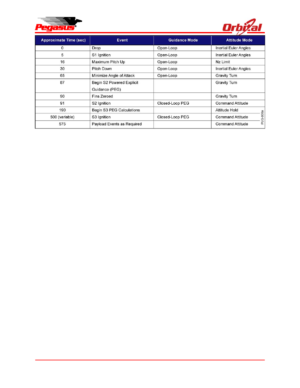
Figure 2-5. Typical Attitude and Guidance Modes Sequence