Pegasus user’s guide – Orbital Pegasus User Manual
Page 44
Release 7.0
Apr 2010
33
Pegasus User’s Guide
5.3.1. Standard Electrical Interface
The standard electrical interface between the
Pegasus launch vehicle and a payload using a
nominal 38” separation system is shown in
Figure 5-10. In this case standard electrical
interface between the Pegasus launch vehicle and
payload is two 42-pin MIL-C-38999 Series II
electrical connectors located at the separation
plane. These connectors are located at launch
vehicle clocking angles of 0º and 180º. This
provides symmetric connector pull forces during
separation to minimize payload tip-off rates. The
circuits that cross this interface will be
documented in a mission-specific Electrical
Interface Control Document (EICD).
As shown in the figure, the standard electrical
interface provides:
• Ten pass-through wires (five twisted shielded
wire pairs) between the payload interface
plane and electrical support equipment
installed in the Orbital Carrier Aircraft,
• Up to six breakwire circuits to be used by the
payload to sense separation from the launch
vehicle, and
• Two breakwire circuits to be used by the
launch vehicle to sense separation of the
payload.
The ten pass-through wires may be used for
payload direct power, battery charging, command
and telemetry transmission, safety inhibits, battery
relay control and/or analog instrumentation. The
current on each circuit is limited to 2.25 A. The six
breakwire circuits are typically split evenly
between the two connectors at the interface plane
but may be configured as required by the payload.
The payload shall provide one launch vehicle
breakwire in each connector on the payload side
of the electrical interface. This provides a
redundant means of sensing payload separation
and allows positive confirmation that both
electrical connectors at the interface plane
separated properly.
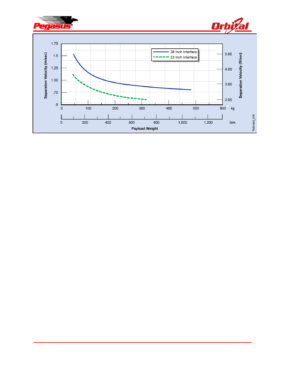
Figure 5-9. Payload Separation Velocities Using the Standard Separation System