3safe configuration – Lenze E84Dxxxxx User Manual
Page 39
Lenze · 8400 protec · Drive-based safety · Software Manual · DMS 2.4 EN · 05/2013 · TD05
39
3
Safe configuration
3.6
Safety bus
_ _ _ _ _ _ _ _ _ _ _ _ _ _ _ _ _ _ _ _ _ _ _ _ _ _ _ _ _ _ _ _ _ _ _ _ _ _ _ _ _ _ _ _ _ _ _ _ _ _ _ _ _ _ _ _ _ _ _ _ _ _ _ _
Status byte
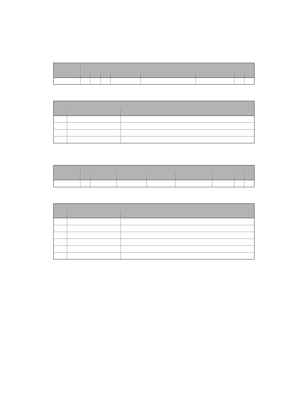
For the PROFIsafe V1 mode, only the given bits of the PROFIsafe status byte are supported:
[3-6]
Structure of the PROFIsafe status byte in V1 mode
[3-7]
Detailed specification of the status byte in V1 mode
For the PROFIsafe V2 mode, only the given bits of the PROFIsafe status byte are supported:
[3-8]
Structure of the PROFIsafe status byte in V2 mode
[3-9]
Detailed specification of the control byte in V2 mode
Assignment
Bit
Byte
7
6
5
4
3
2
1
0
4
-
-
-
FV_activated
COM-Failure WD-Timeout
COM-Failure CRC
-
-
Bit coding of status byte
Bit
Name
Meaning
2 COM-Failure CRC
Status is active after communication error.
3 COM-Failure WD-Timeout
Status is active after time-out.
4 FV_activated
The PROFIsafe input data are passivated.
-
Reserved for future extensions.
Assignment
Bit
Byte
7
6
5
4
3
2
1
0
4
-
cons_nr_R
Toggle_d
FV_activated
WD-Timeout
CE_CRC
-
-
Bit coding of status byte
Bit
Name
Meaning
2 CE-CRC
Status is active after communication error.
3 WD-Timeout
Status is active after time-out.
4 FV_activated
The PROFIsafe input data are passivated.
5 Toggle_d
Change shows an increase of the consecutive number.
6 cons_nr_R
Consecutive number has been reset.
-
Reserved for future extensions.