5 diagnostics & error management, Diagnostics & error management, 2introduction – Lenze E84Dxxxxx User Manual
Page 20
2
Introduction
2.5
Diagnostics & error management
20
Lenze · 8400 protec · Drive-based safety · Software Manual · DMS 2.4 EN · 05/2013 · TD05
_ _ _ _ _ _ _ _ _ _ _ _ _ _ _ _ _ _ _ _ _ _ _ _ _ _ _ _ _ _ _ _ _ _ _ _ _ _ _ _ _ _ _ _ _ _ _ _ _ _ _ _ _ _ _ _ _ _ _ _ _ _ _ _
2.5
Diagnostics & error management
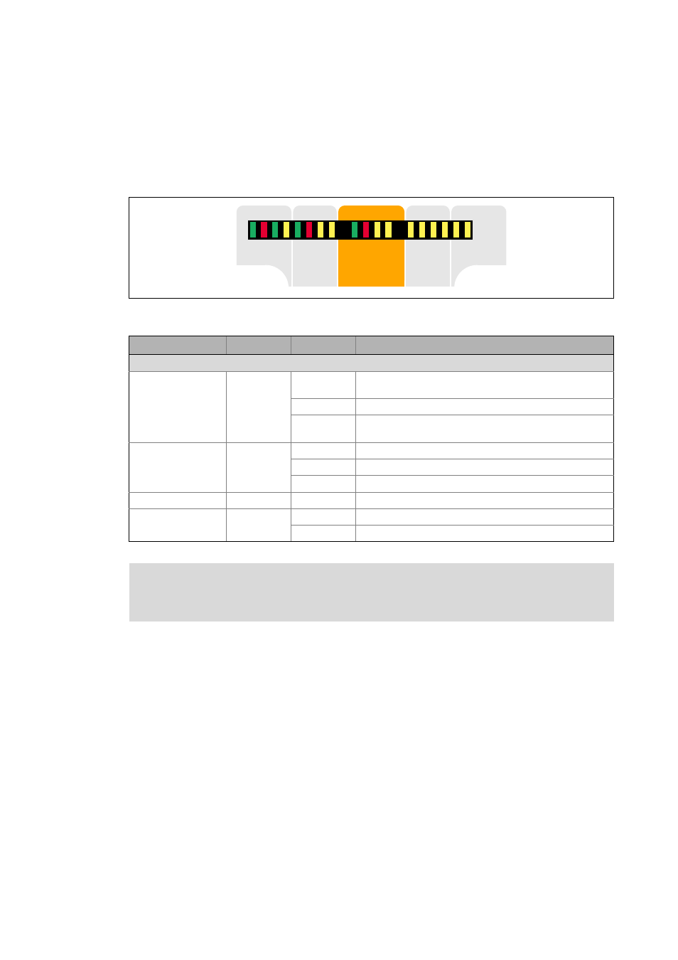
LED display
In the "Safety" field in the middle of the LED display on the front of the controller you will get
information on the status of the drive-based safety system:
[2-2]
LED display on the front of the controller
',
',
','2
','2
',
',
5'<
(55
9
6
%UDNH
%865'<
%86(55
/LQN
/LQN
66WDWH
6(UURU
6$FNQZ
6(QDEOH
'5
9
6WDWXV
&RP
6DIHW\
,2
,2
Labelling
Colour
Status
Description
LED status displays for the integrated safety system
S-State
green
off
Communication between standard device and safety system
is not possible
blinking
Integrated safety system is in the service status
on
Communication between standard device and safety system
has been established
S-Error
red
off
Error-free operation
blinking
Integrated safety system is not accepted by standard device
on
Warning/fault/error
S-Acknw
yellow
on
Parameter set acceptance must be acknowledged
S-Enable
yellow
blinking
Safety function active (non-safe display)
on
Controller enabled
Note!
The status of safety option 10 is only indicated via the "S-Enable" LED display.