Parameters, 5 custom motor data entry, 1 electrical & mechanical constants – Lenze E94P PositionServo with MVOB User Manual
Page 45
S94H201E_13426446_EN
L
43
Parameters
8.
Click [Save File] to save the completed motor file (use same filename as the initial data in step 1).
Click [Update Drive] to load the motor data to the drive.
5.2.5
Custom Motor Data Entry
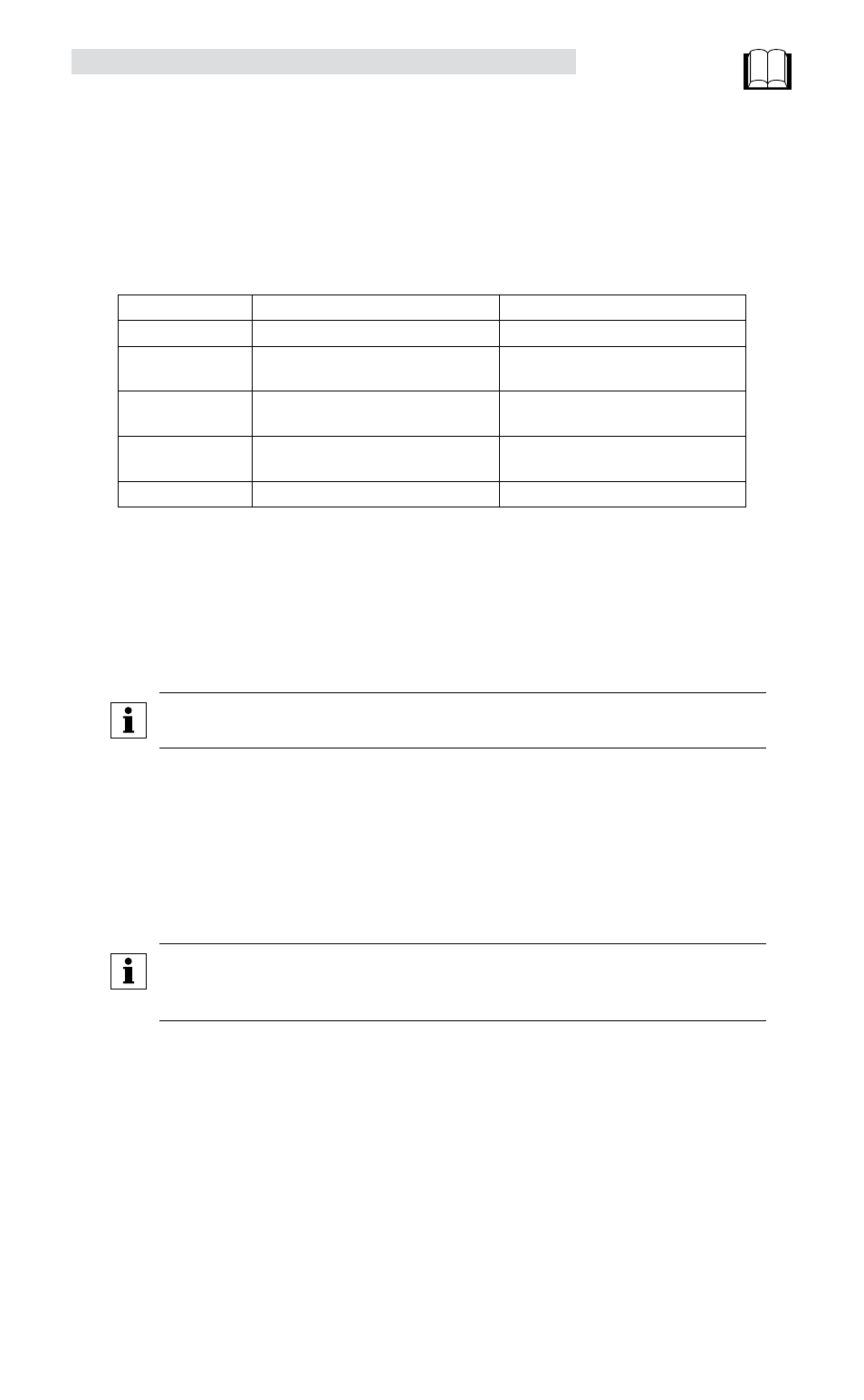
A Custom Motor file is created by entering motor data into the “Motor Parameters” dialog box. This box
is divided up into four sections: Electrical constants, Mechanical constants, Feedback and Gain Scaling.
Parameter Type
Synchronous Motor
Asynchronous (Induction) Motor
Identification
Vendor, Motor Model, ID
Vendor, Motor Model, ID
Electrical
Kt, Ke, Lm, Rm, I
RMS
, Nominal V
BUS
,
# of poles
Cos
f, f
Base
, Lm, Rm, I
RMS
, Nominal V
BUS
,
# of poles
Feedback
Primary feedback, Resolver Offset
Resolver FB, Encoder PPR before quad,
B leads A CW
Motor Gain Scaling
Velocity P-gain, Velocity I-gain,
Gain Scaling
Velocity P-gain, Velocity I-gain,
Gain Scaling
Mechanical
Jm, Vel
MAX
Jm, Vel
NOMINAL
, Vel
MAX
When creating a custom motor, input the value of all parameters listed for the specific motor type. All
entries are mandatory except motor inertia (Jm). Enter a value of 0 for the motor inertia if the actual value
is unknown.
5.2.5.1 Electrical & Mechanical Constants
Motor Torque Constant (Kt)
Enter the value and select proper units from the drop-down list.
NOTE
Round the calculated result to 3 significant places.
Motor Voltage Constant (Ke)
The program expects Ke to be entered as a phase-to-phase Peak voltage. If you have Ke as an RMS value,
multiply this value by 1.414 for the correct Ke Peak value.
Phase-to-phase winding Inductance (Lm)
This must be set in millihenries (mH). The phase-to-phase winding Inductance (L) will typically be between
0.1 and 200.0 mH.
NOTE
If the units for the phase-to-phase winding Inductance (L) are given in micro-henries
(µH), then divide by 1000 to get mH.
Phase-to-phase winding Resistance (Rm) in Ohms
This is also listed as the terminal resistance (Rt). The phase-to-phase winding Resistance (R) will typically
be between 0.05 and 200 Ohms.
Nominal phase current (RMS Amps)
Nominal continuous phase current rating (In) in Amps RMS. Do not use the peak current rating.