Interface, 3 digital outputs – Lenze E94P PositionServo with MVOB User Manual
Page 34
32
L
S94H201E_13426446_EN
Interface
4.2.2
Buffered Encoder Output (P3, pins 7-12)
There are many applications where it is desired to close the feedback loop to an external device. This
feature is built into the PositionServo drive and is referred to as the “Buffer Encoder Output”. If a motor with
encoder feedback is being used, the A+, A-, B+, B-, Z+ and Z- signals are directly passed through the drive
through pins 7-12 with no delays, up to a speed of 2MHz. If a motor with resolver feedback is being used
a minimal encoder feedback is transmitted. The default resolution of the simulated encoder is 1024 pulses
per revolution, pre-quad. If a different resolution is desired refer to section 5.3.19 “Resolver Tracks”. There
is a small additional delay when using a resolver. With Encoder pass through the delay is approximately
100nS; with Resolver pass through, the delay is approximately 62uS. Refer to Note 1 in section 4.1.7.
4.2.3
Digital Outputs
There are a total of five digital outputs (“OUT1” - “OUT4” and “RDY”) available on the PositionServo drive.
These outputs are accessible from the P3 connector. Outputs are open collector/emitter and are fully
isolated from the rest of the drive circuits as shown in the figures below. These outputs can be used by the
drive’s internal User Program or they can be configured as Special Purpose outputs. When used as Special
Purpose, each output (OUT1-OUT4) can be assigned to one of the following functions:
•
Not assigned
•
Zero speed
•
In-speed window
•
Current limit
•
Run-time fault
•
Ready
•
Brake (motor brake release)
Note that if an output is assigned as a Special Purpose Output then that output can
not be utilized by the
User Program. The “RDY” Output has a fixed function, “ENABLE”, that will become active when the drive is
enabled and the output power transistors become energized.
Digital outputs electrical characteristics
Circuit type
Isolated open collector/emitter
Digital outputs load capability
100mA
Digital outputs Collector-Emitter max voltage
30V
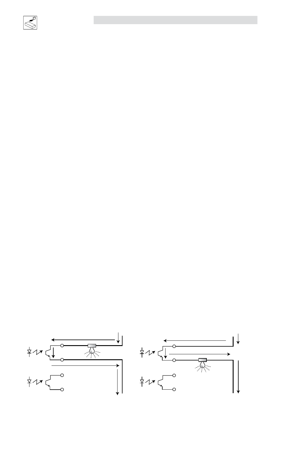
The digital outputs have a typical 1 volt leakage. Apply the appropriate relays based on the application. The
outputs on the drive can be wired as either sinking (NPN) or sourcing (PNP), as illustrated herein.
NPN Sinking
OUT 1-C
Gnd
+24V
43
44
45
46
OUT 1-E
OUT 2-C
OUT 2-E
PNP Sourcing
OUT 1-C
Gnd
+24V
43
44
45
46
OUT 1-E
OUT 2-C
OUT 2-E
mb101
mb102