Interface – Lenze E94P PositionServo with MVOB User Manual
Page 32
30
L
S94H201E_13426446_EN
Interface
Test
Step
Action
Drive Display
Indication
Safety Status Output
Indication
Failed Test
Indication
5
Deactivate Safety
Input 2. Set Input A3
to Enable
‘F EF’
‘Activated’
No Trip on display (F_EF) = Safety Input 2 failed to deactivate.
Status Output Deactivated = Safety Input 1 Failed to activate
6
Set Input A3 to disable
‘Dis’
‘Activated’
Status Output Deactivated = Both Safety Inputs Failed to
activate
7
Deactivate Safety
Input 1. Set Input A3
to Enable
‘F EF’
‘Deactivated’
No Trip on display (F_EF) = Safety Inputs 1 & 2 failed to
deactivate.
Status Output Activated = Safety Input 1 or Safety Input 2
Failed to deactivate
This procedure will evaluate the following conditions:
a.
All Circuits (safety inputs 1 & 2) working Correctly
b.
Safety Input 1 failing to activate
c.
Safety Input 1 failing to deactivate
d.
Safety Input 2 failing to activate
e.
Safety Input 2 failing to deactivate
f.
Both Safety input 1 and 2 failing to activate
g.
Both Safety input 1 and 2 failing to deactivate
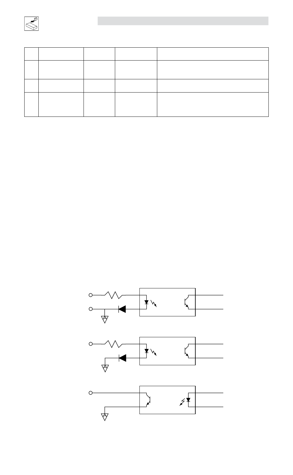
Electrical Characteristics
Safety Input1, Safety Input2 and Safety Status are fully isolated from the rest of the drive circuits as shown
in the following diagram.
Safety Inputs
Insulated, compatible with single-ended output (+24VDC)
Enable voltage range: 18 to 30VDC
Disable voltage range: 0 to 1.0 VDC
Input Impedance
6.8 k
Ω
Safety Status
Isolated Open Collector (Grounded Emitter)
Output Load Capability
100mA
Output Max Voltage
30VDC (Collector-Emitter)
Safety Status
Safety Input 2
Safety Input 1
Safety COM
SAFETY COM
SAFETY COM
SAFETY COM
6.8kΩ
6.8kΩ
1
1
1
2
2
2
3
3
3
4
4
4
A
A
A
C
C
C
E
E
E
K
K
K