Interface, 3 analog i/o details, 1 analog reference input – Lenze E94P PositionServo with MVOB User Manual
Page 36
34
L
S94H201E_13426446_EN
Interface
4.3
Analog I/O Details
4.3.1
Analog Reference Input
AIN1+, AIN1- (P3.24 and P3.25)
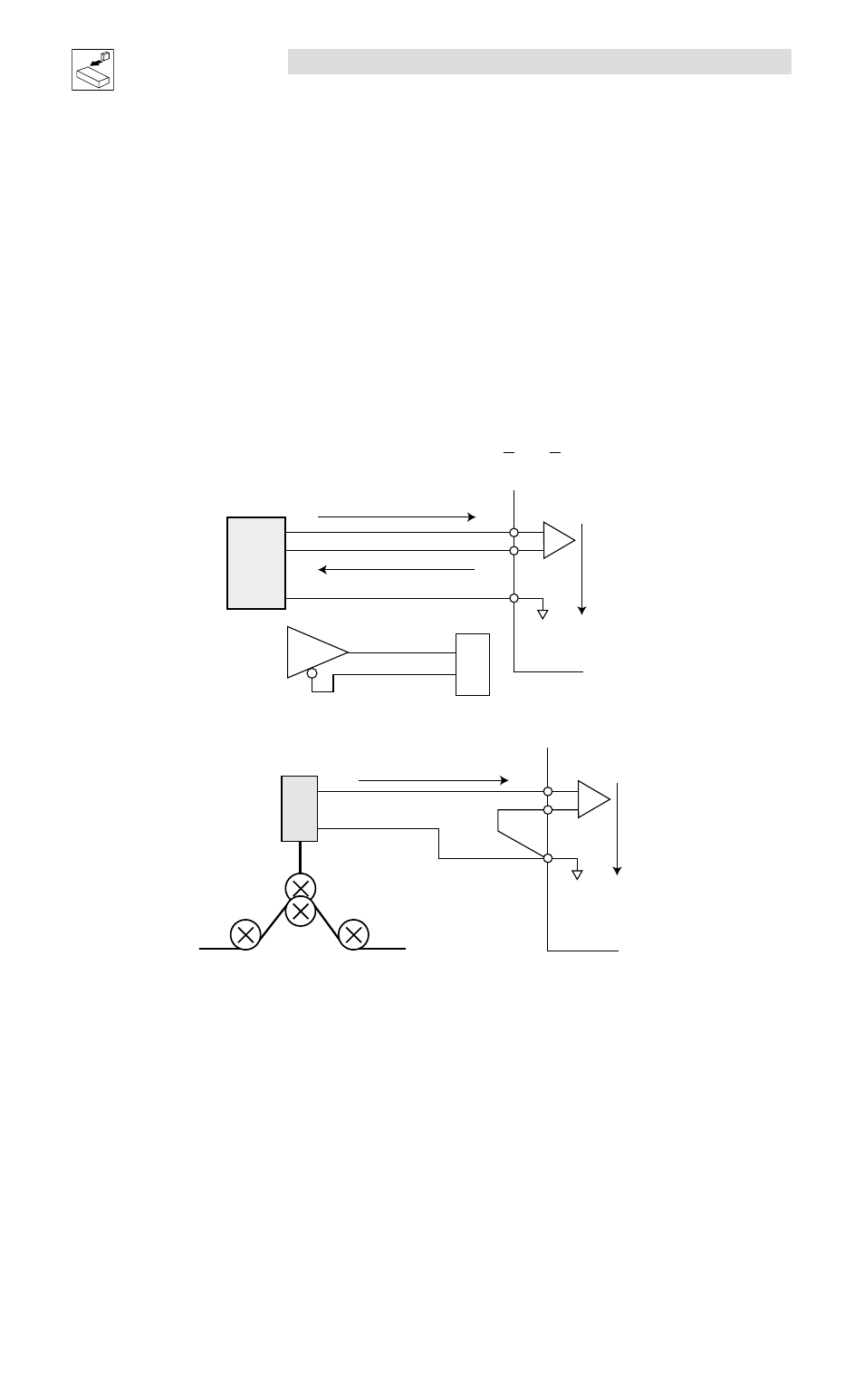
The analog reference input can accept up to a ±10V analog signal across AIN1+ and AIN1-. The maximum
limit with respect to analog common (ACOM) on each input is ±18VDC. The analog signal will be converted
to a digital value with 12 bit resolution (11-bit plus sign). This input is used to control speed or torque of the
motor in velocity or torque mode. The total reference voltage as seen by the drive is the voltage difference
between AIN1+ and AIN1-. If used in single-ended mode, one of the inputs must be connected to a voltage
source while the other one must be connected to Analog Common (ACOM). If used in differential mode, the
voltage source is connected across AIN1+ and AIN1- and the driving circuit common (if any) needs to be
connected to the drive Analog Common (ACOM) terminal. Refer to the External Reference and Single-Ended
Configuration wiring examples below.
Reference as seen by drive: Vref = (AIN1+) - (AIN1-) and -10V < Vref < +10V
External Reference
(Differential Configuration)
ACOM
Analog Command Output
Analog Command Return
ACOM
P3.24
P3.25
P3.22
AIN-
AIN+
PostionServo
Drive
940 Servo Drive
+
-
Analog input +
Analog input -
A
nalog I
nput
Motion
Controller
mb105
Single-ended Configuration
ACOM
AOut
P3.20
P3.21
P3.22
AIN-
AIN+
PositionServo
Drive
ACOM
As the dancer arm goes up and down
a 0 - 10 volt signal is transmitted
to the PositionServo Drive.
+
-
mb106
AIN2+, AIN2- (P3.20 and P3.21)
The analog reference input can accept up to a ±10V analog signal across AIN2+ and AIN2-. The maximum
limit with respect to analog common (ACOM) on each input is ±18VDC. The analog signal will be converted
to a digital value with 12 bit resolution (11-bit plus sign). This input is available to the User’s program. This
input does not have a predefined function.