Interface, 5 p5 - 24 vdc back-up power input, 6 p6 - braking resistor and dc bus – Lenze E94P PositionServo with MVOB User Manual
Page 26
24
L
S94H201E_13426446_EN
Interface
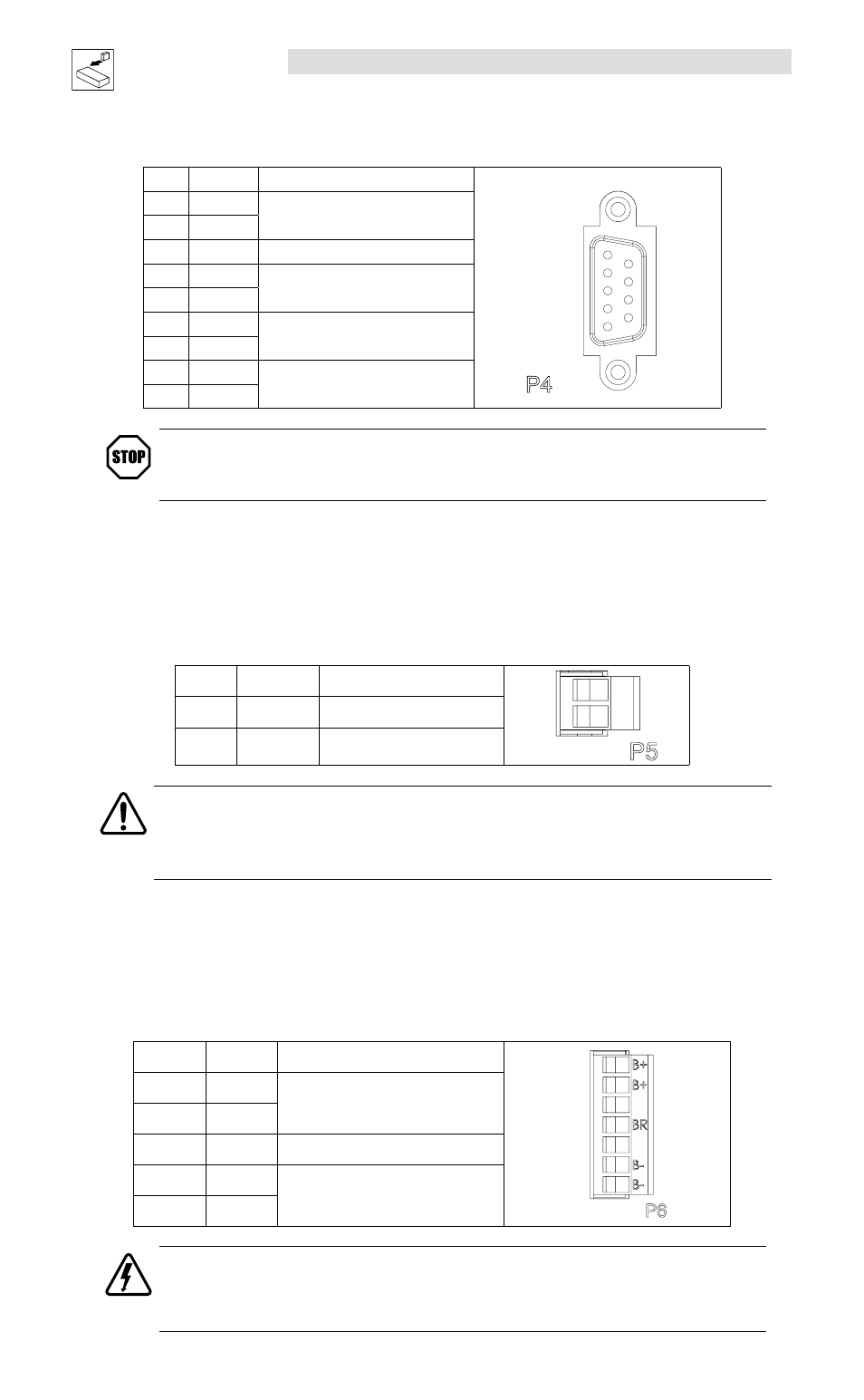
P4B Pin Assignments (Resolver Feedback - E94R Drives)
Pin
Name
Function
RESOL
VER
1
5
P4
9
6
1
Ref +
Resolver reference connection
2
Ref -
3
N/C
No Connection
4
Cos+
Resolver Cosine connections
5
Cos-
6
Sin+
Resolver Sine connections
7
Sin-
8
PTC+
Motor PTC Temperature Sensor
9
PTC-
STOP!
Use only 10 V (peak to peak) or less resolvers. Use of higher voltage resolvers may result
in feedback failure and damage to the drive.
4.1.5
P5 - 24 VDC Back-up Power Input
P5 is a 2-pin quick-connect terminal block that can be used with an external 24 VDC (500mA) power supply
to provide “Keep Alive” capability: during a power loss, the logic and communications will remain active.
Applied voltage must be greater than 20VDC.
P5 Pin Assignments (Back-up Power)
Pin
Name
Function
+
-
+
-
24
1
+24 VDC
Positive 24 VDC Input
2
Return
24V power supply return
WARNING!
Hazard of unintended operation! When the enable input remains asserted, the “Keep Alive”
circuit will restart the motor upon restoration of mains power. If this action is not desired,
then remove the enable input prior to re-application of input power.
4.1.6
P6 - Braking Resistor and DC Bus
P6 is a 5-pin quick-connect terminal block that can be used with an external braking resistor (the
PositionServo has the regen circuitry built-in). The Brake Resistor connects between the Positive DC Bus
(either P6.1 or 2) and P6.3.
P6 Terminal Assignments (Brake Resistor and DC Bus)
Pin
Terminal Function
B+
B-
BR
B-
B+
1
B+
Positive DC Bus / Brake Resistor
2
B+
3
BR
Brake Resistor
4
B-
Negative DC Bus
5
B-
DANGER!
Hazard of electrical shock! Voltage up to 480 VAC above earth ground is possible. Avoid direct contact
with live terminals and circuit elements. Disconnect incoming power and wait 60 seconds before
opening or servicing the drive. Capacitors retain charge after power is removed.