Installation – Lenze EMF2181IB User Manual
Page 25
Installation
Electrical installation
Connection for the CAN bus
l
25
EDSMF2181IB EN 3.0
Bus cable length
)
Note!
ƒ
It is absolutely necessary to comply with the permissible cable lengths.
ƒ
Please note the reduction of the total cable length due to the signal delay of
the repeater (
¶ 27).
ƒ
Mixed operation
– Mixed operation refers to different nodes which are connected to the
same network.
– If the total cable lengths of the nodes are different at the same baud rate,
the smaller value must be used to determine the max. cable length.
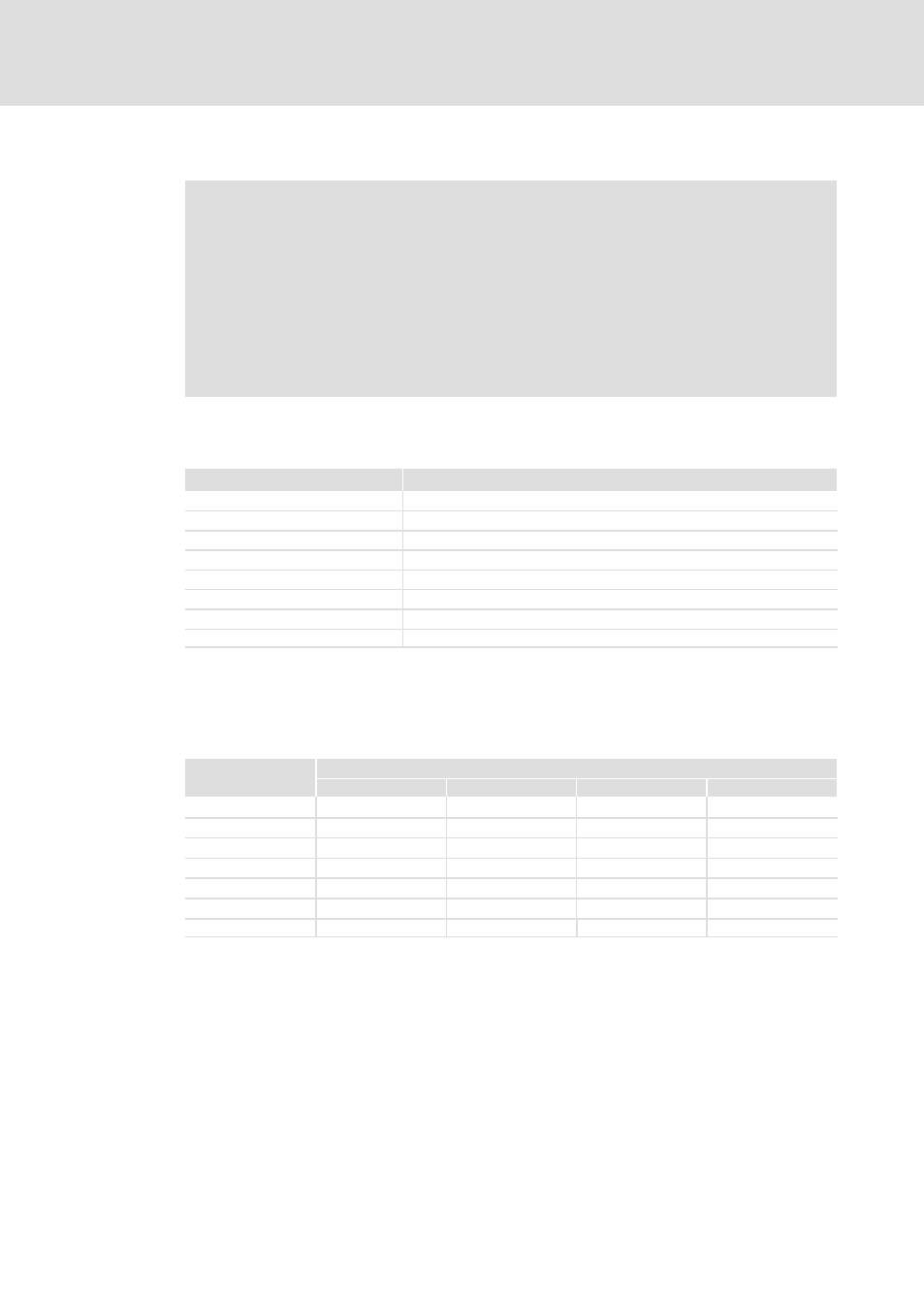
1. Please check the compliance with the total cable length in Tab. 5−1.
The total cable length is determined by the baud rate.
Baud rate [kbit/s]
Max. bus length [m]
10
8000
20
3900
50
1500
125
630
250
290
500
110
800
40
1000
17
Tab. 5−1
Total cable length
2. Please check the compliance with the segment cable length in Tab. 5−2.
The segment cable length is specified by the cable cross−section and the number of nodes.
Without a repeater, the segment cable length corresponds to the total cable length.
Max. number of
nodes per segment
Cable cross−section
0.25 mm
2
0.5 mm
2
0.75 mm
2
1.0 mm
2
2
240 m
430 m
650 m
940 m
5
230 m
420 m
640 m
920 m
10
230 m
410 m
620 m
900 m
20
210 m
390 m
580 m
850 m
32
200 m
360 m
550 m
800 m
63
170 m
310 m
470 m
690 m
100
150 m
270 m
410 m
600 m
Tab. 5−2
Segment cable length
3. Compare both values.
If the value given in Tab. 5−2 is smaller than the total cable length given in Tab. 5−1,
repeaters must be used. Repeaters divide the total cable length into segments.