2 electrical installation, 1 emc-compliant wiring, 2 network topology – Lenze E84AYCIB User Manual
Page 27: Electrical installation, Emc-compliant wiring, Network topology, Network topology ( 27), E84aycib communication manual (interbus)
EDS84AYCIB EN 4.0 - 11/2010
L
27
E84AYCIB communication manual (INTERBUS)
Installation
Electrical installation
5.2
Electrical installation
5.2.1
EMC-compliant wiring
In typical systems, standard shielding of the Ethernet cables is sufficient.
However, in environments with a very high level of interference, EMC resistance can be
improved by additionally earthing the cable shield on both sides.
For this observe the following notes:
1. Remove the plastic sheath of the cable on a length of 2 cm.
2. Fasten the cable shield onto the shield contact of the standard device.
5.2.2
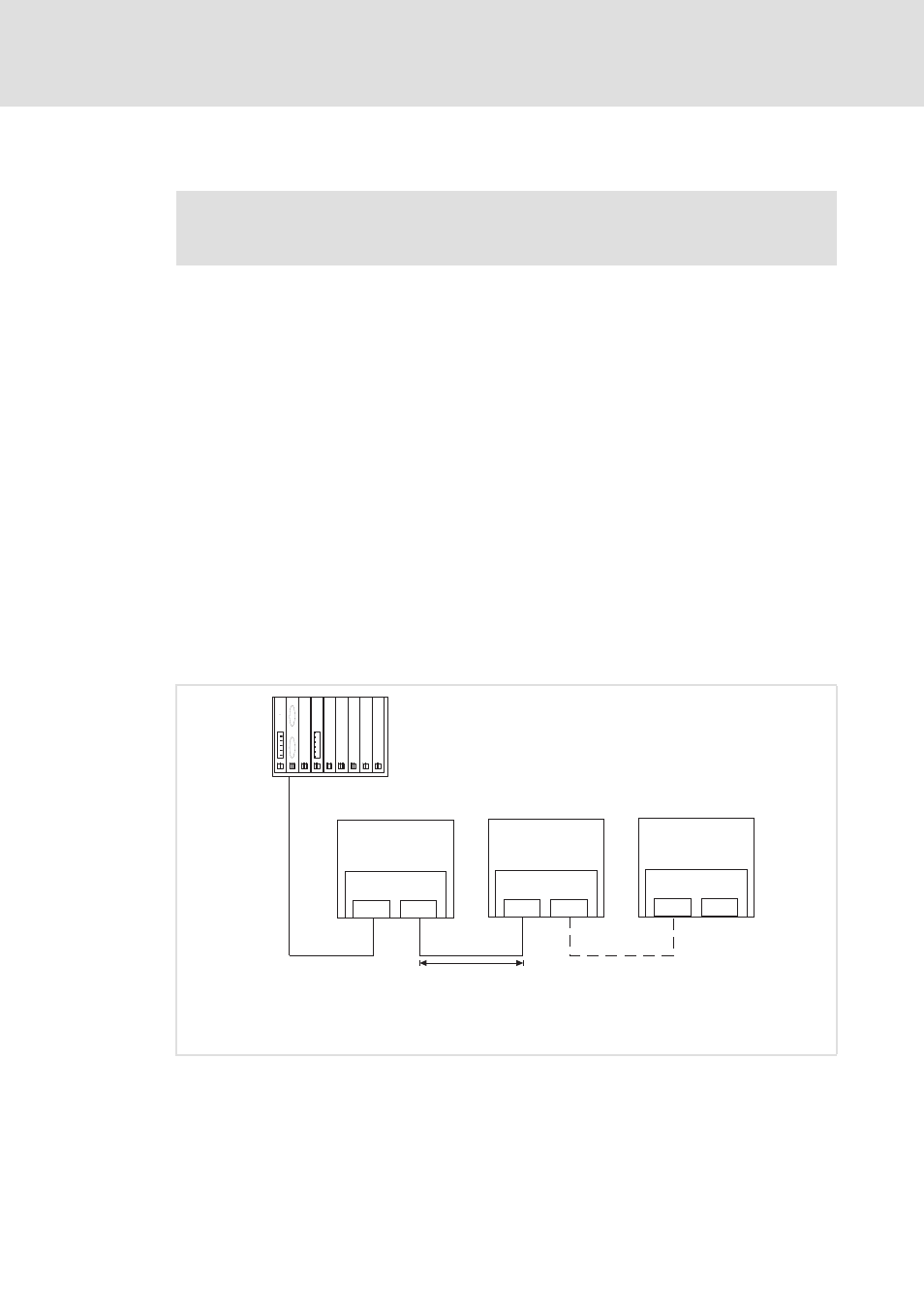
Network topology
The bus system must be designed as a ring. Feed and return lines must be integrated in the
same bus cable. The ring goes from the INTERBUS master via all other nodes and back again
to the master.
An INTERBUS ring can consist of maximally 513 nodes (1 master + standard devices
connected).
[5-4]
INTERBUS ring
Documentation for the standard device, control system, plant/machine
Observe the notes and wiring instructions contained in this documentation.
E94YCIB008
M: Master (master control, e.g. PLC, Industrial PC)
S1 ... Sn: Slaves
500 kBit/s:
400 m
2 MBit/s:
£
150 m
£
Inverter Drive
8400
E84AYCIB
X206
X207
Inverter Drive
8400
E84AYCIB
X206
X207
Inverter Drive
8400
E84AYCIB
X206
X207
OUT
IN
OUT
IN
IN
M
S2
S1
Sn