Igure, Olar, Dmittance – INFICON RQCM - Quartz Crystal Microbalance Research System User Manual
Page 65: Lot of, Rystal, Dmittance vs, Requency, Eal and, Maginary, Omponents of
RQCM – RESEARCH QUARTZ CRYSTAL MICROBALANCE
THEORY OF OPERATION
5-13
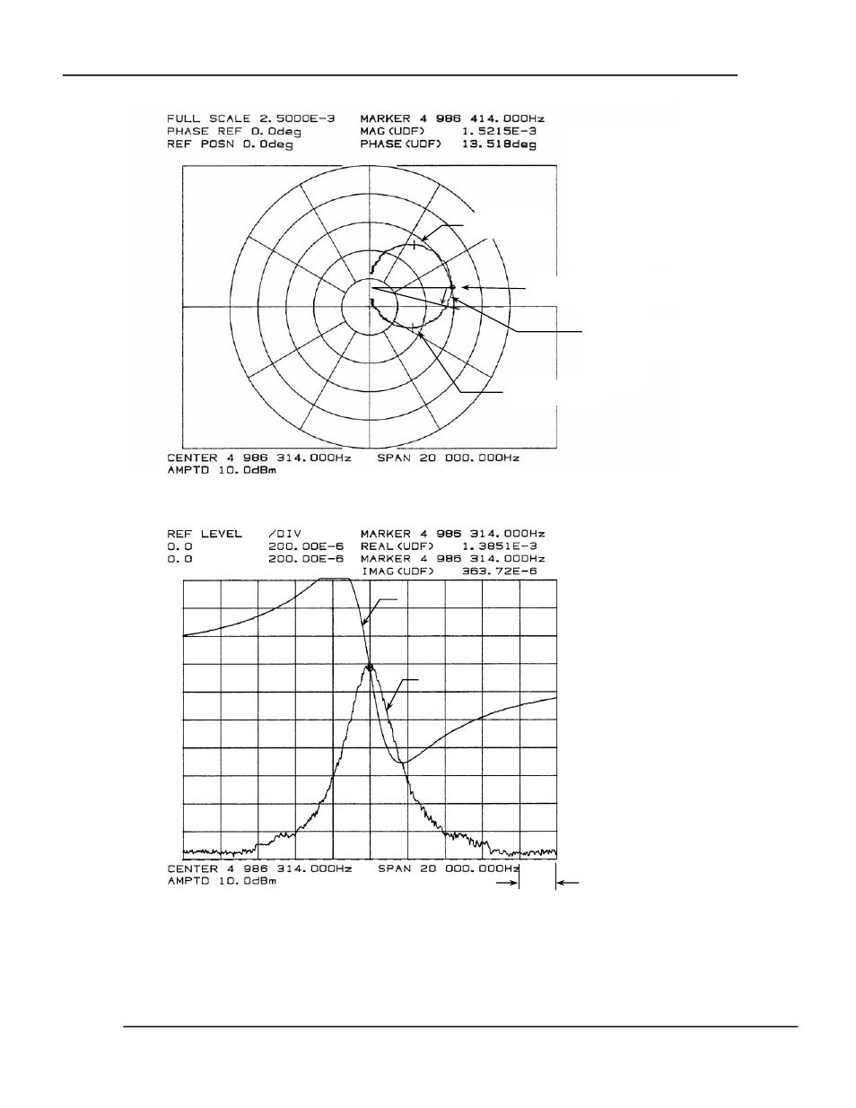
Figure 21 Polar Admittance Plot of Low Q Crystal
Figure 22 Admittance vs. Frequency, Real and Imaginary Components of Low Q Crystal
The conductance of the L, R & C series arm creates the circle in the polar plot with its center on
the real axis. The effect of the shunt capacitance conductance is to offset the circle vertically.
Figure 21 shows a heavily loaded crystal in which the offset is obvious. It is the imaginary
(quadrature) current through the shunt capacitance that creates the offset. The RQCM provides a
(REAL)
CONDUCTANCE
X10
-3
SIEMENS
(IMAGINARY)
SUSCEPTANCE
X10
-3
SIEMENS
140
120
100
80
60
40
20
0
0.8
0.6
0.4
0.2
0
-0.2
-0.4
-0.6
-0.8
IMAGINARY
REAL
2 KHz
FREQUENCY = 4.986414 MHz
RESISTANCE = 657Ω
Q = 1,700
CRYSTAL MEASURED IN GLYCEROL AND WATER
SOLUTION.
FROM AIR TO SOLUTION:
RESISTANCE CHANGED FROM 8.6Ω TO 657Ω
FREQ. CHANGED FROM 4.987966 TO 4.987414 MHz
∆
f = -526 Hz
TRUE SERIES RESONANCE
4.986414 MHz
CIRCLE TOP
4.984964 MHz
CIRCLE BOTTOM
4.987914 MHz
EFFECTIVE PHASE ERROR
BANDWIDTH = BOTTOM – TOP (CIRCLE)
= 4.987914 – 4.984964 MHz
= 2,950 Hz