2 dgsl-…-n without cushioning components, 3 installation, pneumatic, 4 installation, electric – Festo DGSL User Manual
Page 6
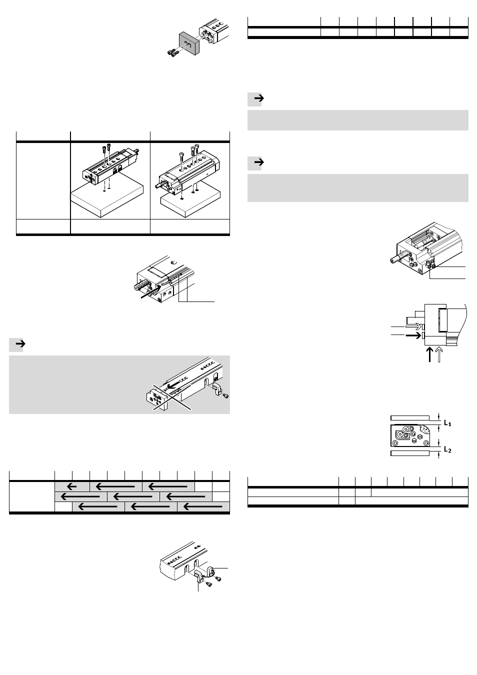
• Screw in two screws for attaching the effective
load:
– into the yoke plate or
– into the slide.
Fig. 5
Installation of the DGSL:
• Use centring sleeves (
Accessories at www.festo.com/catalogue).
• Check whether adapter plates from the Festo multi-axis modular system are
required.
• Fasten the DGSL with the stated minimum number of screws: (
table Fig. 6).
If the slide is pushed into the retracted end position, the through-holes become
accessible.
Stroke
< 50 mm
Stroke
› 50 mm
Base-surface mount-
ing with:
– Threaded holes
– Through-holes
Minimum number of
screws
two
three
Fig. 6
Position sensing of the slide end
positions:
• Place the proximity switches in the
grooves
9.
On the DGSL-4, only SM
T-10
proximity switches are permitted.
• With the DGSL-4/-8, preferably use
the lower groove on the base side.
Fig. 7
9
Rough setting of the end positions:
Note
The DGSL may be damaged if the
slide is moved without a fixed stop.
• Make sure that the slide always re-
mains in the retracted end position
when the fixed stop is dismantled.
Fig. 8
1. Move the slide into the retracted end position.
2. Unscrew the mounting screws of the fixed stop and the required cover
aD
(
Fig. 10).
A reduction of a max. 2 standard strokes is possible (for DGSL-…-E the standard
stoke range cannot be completely covered).
Stroke
0
10
20
30
40
50
80
100
150
200
Stroke reduc-
tion
1)
Fig. 9
1)
Not for DGSL-…-E
3. Replace the fixed stop
6 with the cover aD.
4. Screw the fastening screws in again. The tightening
torque is summarised in the following table
(
Fig. 11).
Fig. 10
aD
6
DGSL
4
6
8
10
12
16
20
25
Tightening torque
[Nm]
0.76
1.3
1.3
2.9
2.9
6
9
9
Fig. 11
5. Complete the precision adjustment of the end positions on the cushioning com-
ponents (
6 Commissioning).
5.2 DGSL-…-N without cushioning components
Note
Operating the DGSL-…-N without shock absorbers will destroy the DGSL.
• Make sure that the DGSL is operated only with cushioning.
Cushioning components for retrofitting cushioning can be ordered separately and
installed in the DGSL subsequently (
10 Accessories).
Note
• Make sure that the following specifications are complied with:
– Max. permissible stop force (
12 Technical data),
– Use of safeguards (e.g. cover cap
10 Accessories).
5.3 Installation, pneumatic
• Use one-way flow control valves for setting the
speed of the slide.
These are screwed directly into the compressed
air supply ports.
With size DGSL-4/-6, L-shaped restrictors on the
front of the supply port enable unhindered ac-
cess for cushioning setting (
Accessories at
www.festo.com/catalogue).
Fig. 12
aA
aJ
• Remove the transport covers on the compressed
air supply ports.
• Connect the tubing to the compressed air supply
ports:
–
aJ retracting
–
aA advancing
The connecting threads must be sealed. The al-
ternative connections
aB and aC to the com-
pressed air supply ports intended at the factory
are prefabricated for the DGSL. They are sealed
with blanking plugs.
Fig. 13
aA
aB
aJ
aC
5.4 Installation, electric
For position sensing with proximity switches:
• Observe the minimum distances L
1
and L
2
between static or moving ferritic masses and the
proximity sensors (
Fig. 14).
In this way you will avoid maloperation as a
result of external influences.
Fig. 14
DGSL
4
6
8
10
12
16
20
25
L1 to ferritic materials
[mm]
5
5
0
L2 to ferritic materials
15
0
Fig. 15