Mini slide dgsl english, 1 control sections and connections, 2 function and application – Festo DGSL User Manual
Page 5: 3 transport and storage, 4 requirements for product use, 5 installation, 1 installation, mechanical, Dgsl
DGSL
Festo AG & Co. KG
Postfach
D-73726 Esslingen
++49/711/347-0
www.festo.com
Operating instructions
8024555
1301e
Original: de
Mini slide DGSL
English
. . . . . . . . . . . . . . . . . . . . . . . . . . . . . . . . . . . . . . . . . . . . . .
Note
Installation and commissioning is to be carried out only by qualified personnel in
accordance with the operating instructions.
1
Control sections and connections
1
5
8
6
7
3
9
aJ
2
3 4
aA
aB
aC
1 Cushioning component:
– elastic (DGSL-…
-E/-P/-P1
– hydraulic (DGSL-…
-Y3/-Y11)
– without (DGSL-…
-N)
2 Drill hole for mounting the mini
slide (lies concealed)
3 Threaded with centring recess for
fastening the effective load
(centring sleeves included in scope
of delivery)
4 Slide/bearing guide
5 Yoke plate
6 Fixed stop
7 Threaded with centring recess for
fastening the mini slide
8 Piston rod
9 Slot for proximity sensor
aJ Compressed air supply port
(retracting)
aA Compressed air supply port
(advancing)
aB Compressed air supply port
(advancing) with blanking screw
1)
aC Compressed air supply port
(retracting) with blanking screw
1)
1)
condition on delivery
Fig. 1
2
Function and application
The DGSL mini slide is a non-rotating single-piston drive with roller bearing guide.
When the compressed air supply ports are pressurized reciprocally, the slide
moves backwards and forwards. On the DGSL-…-E/-P/-P1, the slide is braked by
elastic cushioning components, on the DGSL-…-Y3/-Y11 by hydraulic shock ab-
sorbers.
The DGSL mini slide is intended for the space-saving transport of masses. A high
degree of positioning accuracy is achieved.
3
Transport and storage
• Take into account the weight of the DGSL.
Depending on the version, the DGSL can weigh up to 7 kg.
• Make sure storage conditions are as follows:
– Short storage times and
– Store in cool, dry, well-shaded corrosion-resistant storage areas.
4
Requirements for product use
Note
Malfunctions will occur if the device is incorrectly used.
• Make sure that the specifications contained in this chapter are adhered to at
all times.
• Note the warnings and instructions on the product and in the relevant operat-
ing instructions.
• Compare the limit values in these operating instructions with those of your
application (e.g. forces, torques, temperatures, masses, speeds).
Operation of the product in compliance with the relevant safety regulations is
contingent on adherence to the load limits.
• Take into consideration the ambient conditions at the location of use.
Corrosive environments will reduce the service life of the product (e.g. ozone).
• Comply with the regulations of the trade association, the German Technical
Control Board (TÜV), of the VDE or relevant national regulations.
• Use the product in its original status, without any unauthorised product modific-
ations.
• Remove all transport packing such as foils, caps, cardboard.
Exception:
– possibly covers in the pneumatic connections.
The material used in the packaging has been specifically chosen for its
recyclability (exception: oil paper = residual waste).
• Make sure there is a supply of correctly prepared compressed air
(
12 Technical data).
• Maintain the selected medium for the total service life of the product. Example:
Always use non-lubricated compressed air.
• Pressurize your entire system slowly. There will then be no uncontrolled move-
ments.
For slow start-up pressurisation, use start-up valve type HEL.
• Take the tolerance of the tightening torques into account. Unless otherwise
specified, the tolerance is ±20 %.
5
Installation
Note
For vertical installation:
• Make sure that the slide has reached a stable position when it comes to rest
(e.g. the lowest point or secured with external stops).
5.1 Installation, mechanical
• Handle the DGSL with care so that the slide guide is not damaged.
This could impair the roller bearing function.
• Leave all screws and threaded bolts in their original states, unless you are re-
quested to modify them in these instructions.
For safety reasons they are fixed with screw locking agent.
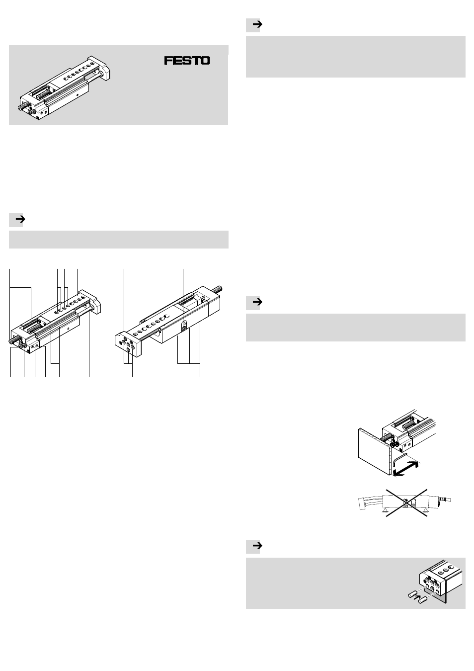
• Make sure there is sufficient space
for the pneumatic connections, the
control sections and for possible
replacement of the cushioning
component and proximity switches.
Fig. 2
• Make sure that the device is installed
free of distortion and deflection.
Fig. 3
Installing the effective load
Note
Driving pins into the yoke plate can damage the
mechanical connection.
• Push a metal plate between the yoke plate and
the housing as a counterholder.
• Then press the required pins into the yoke
plate.
Fig. 4