Connecting ethernet, Connecting linkpower and auxiliary power, Installing the termination pcb in the backbox – ETC Unison Paradigm Touchscreen with Locking Cover User Manual
Page 3: Paradigm p-lcd series
E T C I n s t a l l a t i o n G u i d e
Paradigm P-LCD Series
Unison Paradigm Touchscreen with Locking Cover
Page 3 of 4
Electronic Theatre Controls, Inc.
Connecting Ethernet
Step 1:
Terminate the network wiring in the RJ45 punch down strip using a standard 110 punch
down tool (not provided). Reference the connector label for the CAT5e wire termination
color code. The punch down connector provides insulation displacement. Do not pre-strip
wire.
Step 2:
Snap the connector into the bracket.
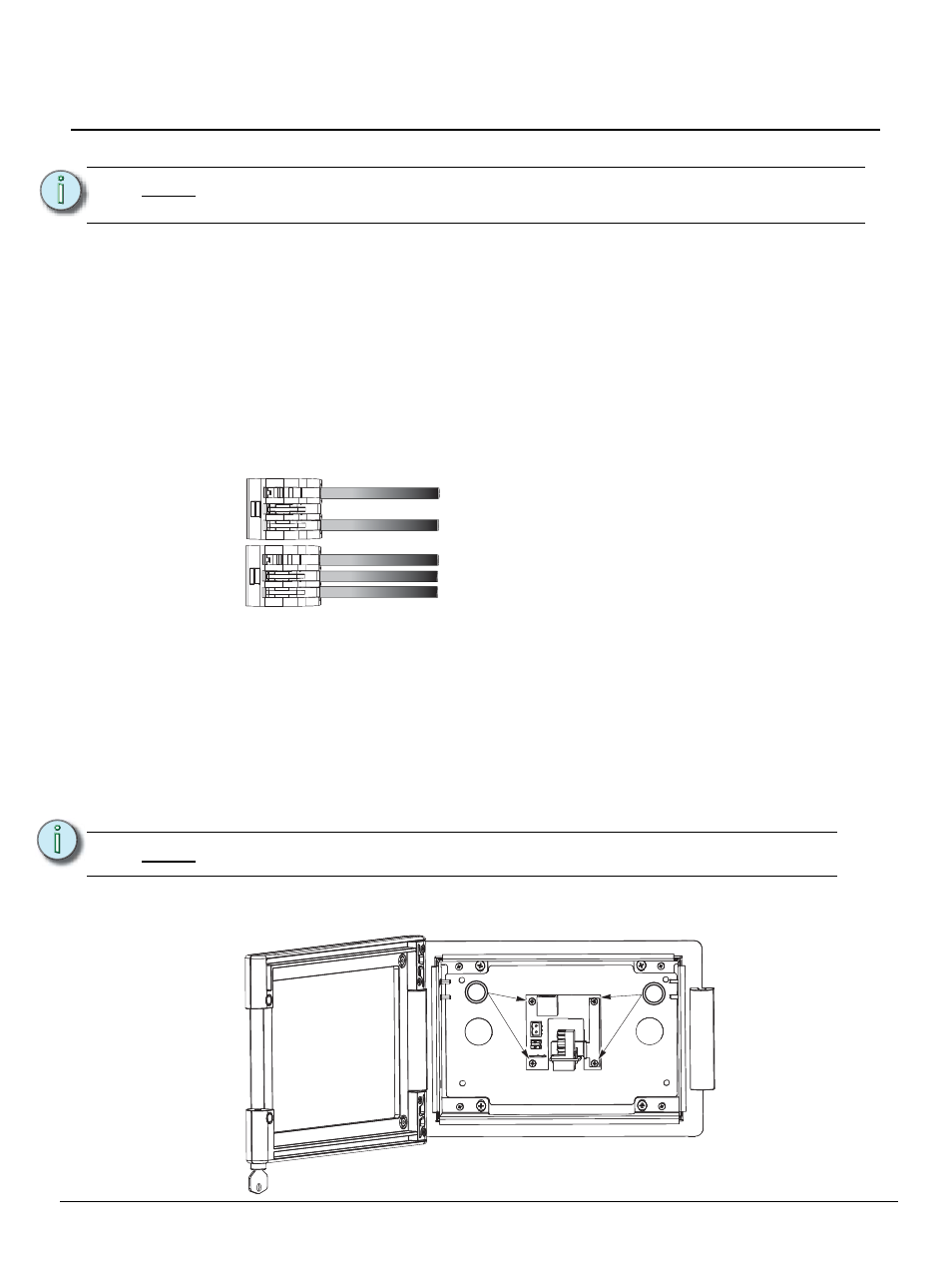
Connecting LinkPower and Auxiliary Power
Use the provided WAGO CAGE CLAMP
®
connectors to terminate the wiring to the provided LinkPower
and Auxiliary power pigtails. Strip the ends of each wire (both installed control wires and pigtail wires)
approximately 3/8” (10mm).
Step 1:
Terminate the installed LinkPower wiring to the white and black LinkPower pigtail. Using
two Wago connectors connect (typically white) installed wire(s) with white pigtail wire and
connect the (typically black) installed wire(s) with black pigtail wire as shown below.
Step 2:
Plug the LinkPower connector into the LinkPower receptacle on the termination PCB.
Step 3:
Terminate the installed Auxiliary power wire to the red and black Auxiliary power pigtail
wires. Using two Wago connectors connect the (typically red) installed wire(s) with red
pigtail wire and connect the (typically black) installed wire(s) with black pigtail wire.
Step 4:
Plug the Auxiliary power connector into the Aux power receptacle on the termination PCB.
Step 5:
A ground connection is required for all Touchscreen assemblies. If the backbox is not
already grounded, attach the ground wire to the ground spade on the PCB.
Installing the Termination PCB in the Backbox
Step 1:
Position the PCB on the four standoffs in the backbox and secure with two M3x10mm pan
head screws on the RJ11 side of the PCB only.
Step 2:
Place the bracket and RJ45 assembly (if used) on top of the PCB. Secure the PCB to the
backbox through the remaining holes in the PCB with two M3x10mm pan head screws.
N o t e :
All Ethernet terminations must follow IEEE 802.3 and be terminated to the T568B
standard.
N o t e :
The termination PCB can be installed in any orientation to accommodate wiring.
topology of a single
station installation
topology of multiple
stations installed in
series
Installed control wire
Pigtail wire
Installed control wire
Installed control wire to next station
Pigtail wire
1
2
PCB installed in a flush mount backbox with collar.