Installing the termination pcb, Paradigm p-lcd series – ETC Unison Paradigm Touchscreen with Locking Cover User Manual
Page 2
E T C I n s t a l l a t i o n G u i d e
Paradigm P-LCD Series
Unison Paradigm Touchscreen with Locking Cover
Page 2 of 4
Electronic Theatre Controls, Inc.
Step 1:
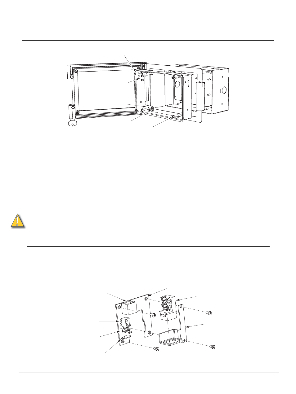
For flush mount applications, thread the four M3 depth adjustment screws into the collar.
Step 2:
Open the locking cover and insert the collar through the opening of the locking cover.
Make sure the Touchscreen mounting pins are at the top.
Step 3:
Insert the collar into the backbox so that the cover frame is flat against the backbox or wall
surface.
Step 4:
For flush mount, adjust the depth adjustment screws (if required) so that the cover is even
against the wall surface.
Step 5:
Install and tighten the four M4 mounting screws through the collar into the backbox.
Installing the Termination PCB
The printed circuit board (PCB) assembly is designed to accommodate either Ethernet or LON
connections. Prior to installing the PCB, terminate all necessary wiring.
The PCB consists of three parts:
• PCB with female RJ11, LinkPower connector, 24 Vdc (Aux) connector, and ground spade
• RJ45 with punch down wire termination
• Mounting bracket and screws
C A U T I O N :
Only one network type can be connected to the touchscreen, not both. Damage may
occur if both power types, Auxiliary power and PoE, are connected to the touchscreen.
ETC requires that all back boxes be grounded in accordance with local electrical
codes. The RJ11 connection must be used to provide a ground connection from the
back box to the touchscreen even when Ethernet connectivity is used.
M3 depth adjustment screw
Touchscreen
mounting pins
Depth adjustment
screw hole
M4 mounting screw
Mounting screw hole
Ground spade
PCB
24 VDC Aux
power
connector
RJ45 Ethernet with
(PoE to Touchscreen)
RJ45
Mounting bracket
LinkPower
connector
RJ11 connector
(provides LinkPower and
Aux power to Touchscreen)