Heading2 - terminate auxiliary power, Paradigm repeater module – ETC Unison Paradigm Repeater Module User Manual
Page 3
E T C S e t u p G u i d e
Paradigm Repeater Module
Paradigm Repeater Module Setup Guide
Page 3 of 4
Electronic Theatre Controls, Inc.
Step 4:
Loosen the terminal screws for the wire pairs you are terminating.
Step 5:
Insert each white (typical) wire from the pairs into a “A” terminal on the connector and
tighten the screw(s) firmly to secure the wire into the terminal.
Step 6:
Insert each black (typical) wire from the pairs into a “B” terminal on the connector and
tighten the screw firmly to secure the wire into the terminal.
Step 7:
The 14 AWG ground wire can terminate to the ground bus located inside the ERn
enclosure.
Step 8:
Replace the connector on the top I/O board.
Terminate Auxiliary Power
Auxiliary power is required when you are installing powered Unison control stations. ETC
recommends using two 16 AWG stranded wires for 24 Vdc auxiliary power to the control station(s).
Auxiliary power is topology-free. Maximum auxiliary voltage runs are dependant by the wire gauge
and the distribution of auxiliary load determined by each installation. The auxiliary supply is capable
of providing 36W (1.5A at 24Vdc).
The auxiliary power connector (labeled Aux Power)
provides termination for up to 20 wires in the ten position
pluggable connector. Each terminal allows up to two 16
AWG wire and provides 24 Vdc power to Unison control
stations when used with the Paradigm ACP.
Step 1:
Pull auxiliary control power wiring (typically 16 AWG red / black wire pair) into the
ERn4 enclosure.
Step 2:
Strip 3/16” (4.8mm) of insulation from the ends of each wire pair.
Step 3:
Remove the auxiliary power connector from the I/O board.
Step 4:
Loosen the terminal screws for the auxiliary wire pairs you are terminating.
Step 5:
Insert the black (typical) auxiliary power wire from the pair into a “-” terminal on the
connector and tighten the screw(s) to secure the wire into the terminal.
Step 6:
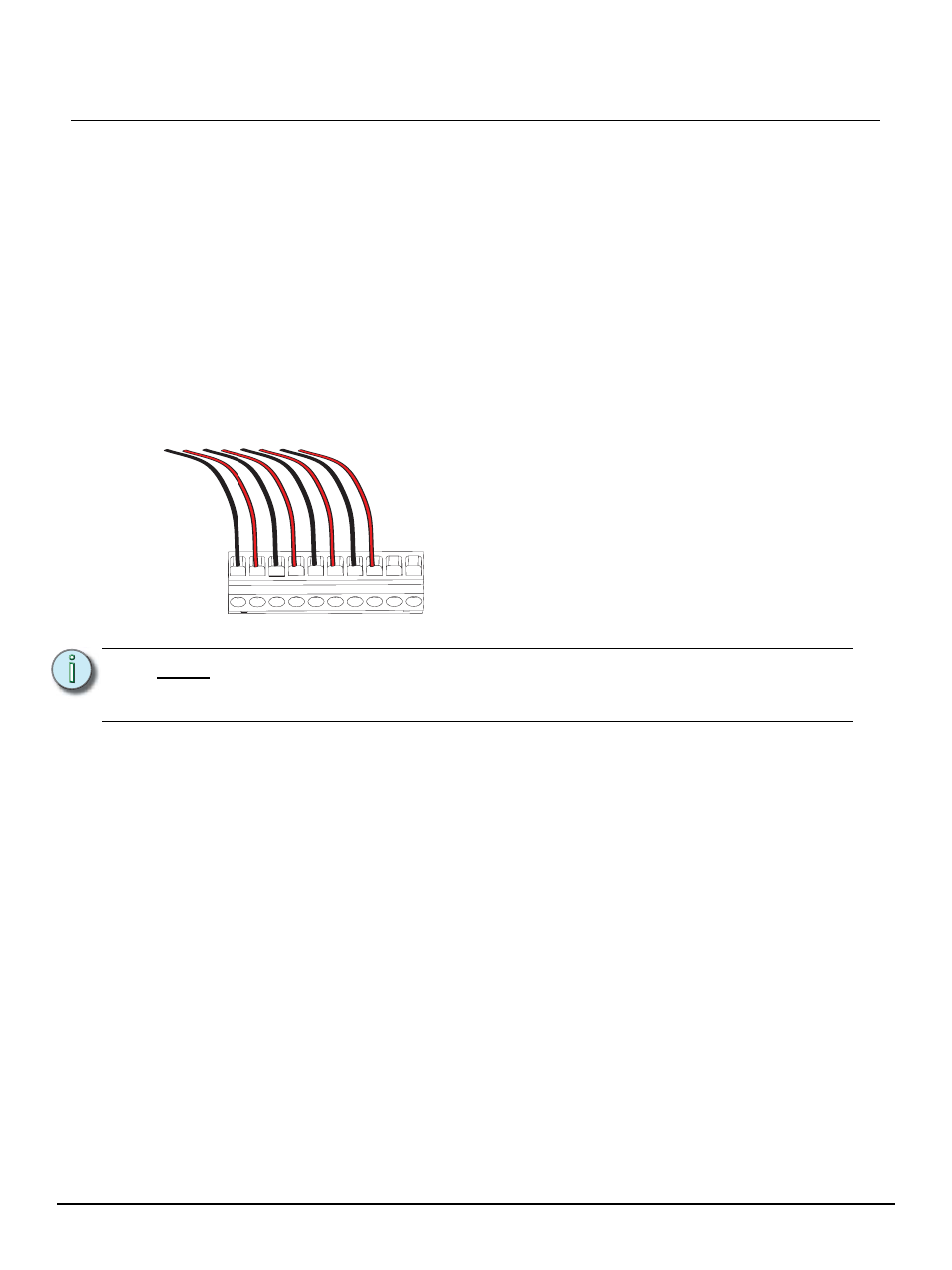
Insert the red (typical) auxiliary power wire from the pair into a “+” terminal on the
connectors and tighten the screw(s) to secure the wire into the terminal.
Step 7:
Replace the connector on the I/O board.
N o t e :
When utilizing a Paradigm station repeater module (P-REP) or Paradigm dual
station repeater module (P-DREP), terminate the affected LON segment(s) and
associated auxiliary power wiring to the top right I/O board in the ERn4 enclosure.
- + - + - + - + - +