ERICO LENTON INTERLOK Rebar Splicing System User Manual
Page 16
10
www.erico.com
1.6 Coupler Installation Procedures at Precasting Plant
C. Install Inlet and Outlet Tubes:
Refer to the Placing Drawings to determine if inlet/outlet tubes are required. If not required (Gravity Fill): Check to make sure
that the inlet/outlet ports are plugged and sealed with the supplied rubber plugs.
If inlet/outlet tubes are required (Pump Fill):
1. Install the inlet and outlet tubes into the ports according to the Placing Drawing Specifications. It is important to
follow these specifications to assure that the ports are correctly located for pump filling and that the tubes are cut to
the correct length. Some experimentation with tube lengths may be necessary to aid in determining proper tube
lengths. Also, it may be necessary to bend the PVC tubes slightly to assure proper port location.
2. Once the tubes have been cut to length and oriented properly, it may be necessary to tap the tubes lightly with a
hammer to assure that they are seated fully inside the ports on the coupler.
3. It is important that the inlet/outlet tubes fit snugly inside the ports on the coupler. If this joint is not tight, apply
adhesive to secure the tubes into the inlet/outlet ports.
4. Once the tubes are positioned, seal the ends of the tubes with rubber stoppers.
D. Inspect The Installation:
To avoid possible intrusion of cement into the LENTON
®
INTERLOK coupler it is important that the following areas be inspected
prior to pouring the precast panel.
1.
Check to see that the LENTON thread is properly installed and tight. Refer to page 9 and the table with wrench
settings.
2.
Make sure inlet/outlet ports are sealed. If tubes are used, make sure tube is tightly seated in the port and that the
opposite end is plugged to prevent entry of concrete. Refer to the Placing Drawings to make sure the inlet/outlet
tubes are located in the correct position for pump filling.
3.
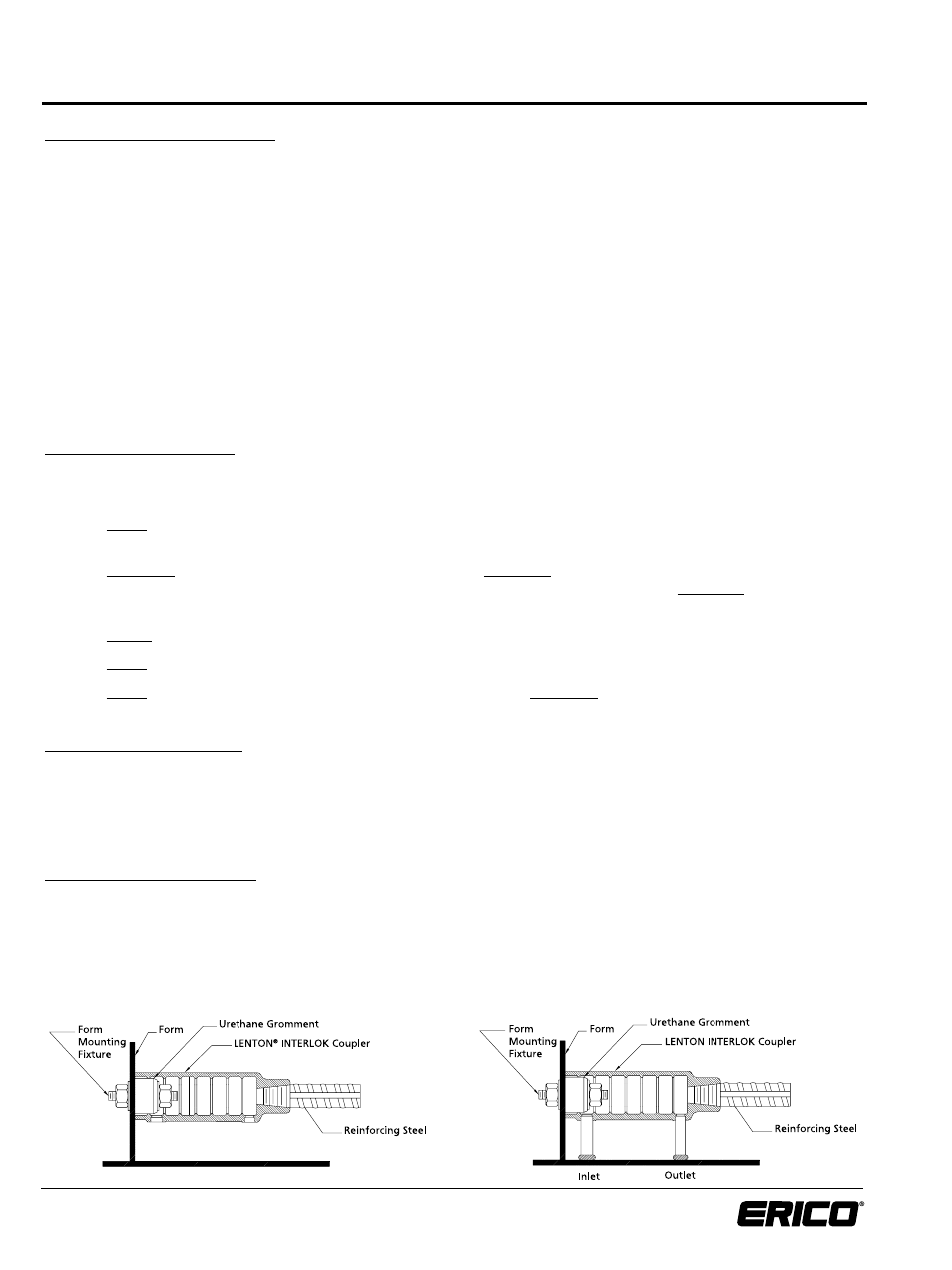
Inspect Form Mounting Fixture and urethane grommet for proper seal to prevent entry of concrete.
4.
Check that the coupler is perpendicular to the form end plate and that it is tightly seated.
5.
Check the length of protruding dowel on opposite end of form. Make sure the dimensions meet those on the
Placing Drawings.
E. Pour Concrete Into Form:
After all other requirements of the Placing Drawings are complete, concrete can be poured.
When pouring the concrete into the form make sure not to disturb any of the PVC tubes as this may cause the tube to slip
out of the inlet/outlet ports or cause the tubes to move away from the outside surface of the form which will make locating
them at the job site difficult.
F. Remove Forms and Inspect:
Once the concrete is cured, remove the Form Mounting Fixtures and the forms, inspect all the inlet/outlet tubes to make sure
that they are clean and free of any blockages and not covered with cement. Any cement inside the coupler or PVC tubes
should be immediately cleaned out.
Finally, to prevent contaminants from entering the clean coupler, insert a plastic dust cover into the open mouth of the coupler.