Sheet6, Drawing view22, Drawing view29 – ERICO IJS100 Insulated Joint Slotter User Manual
Page 6: Drawing view51
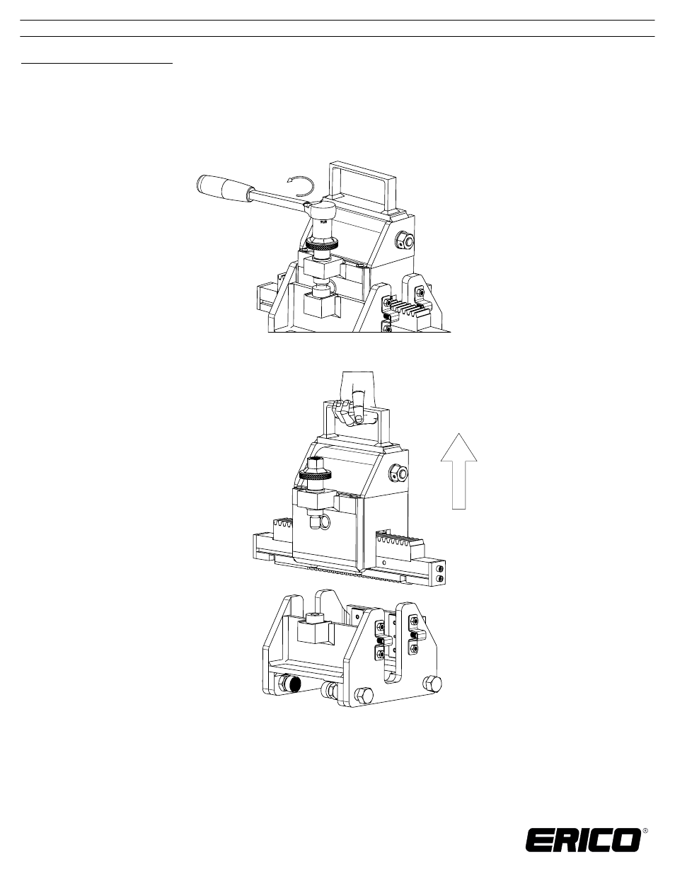
Figure 12: Turn the height adjustment knob to disengage the screw thread
Installation Instructions:
1. Completely read the instructions before attempting to operate this device.
2. Remove the gearbox from the base assembly.
Turn the height adjustment knob counter-clockwise until the screw thread disengages from the
a.
brass nut (Figure 12).
b. Lift the gearbox straight up from the base assembly (Figure 13).
c. Return the gearbox assembly to the carrying case until needed. Do not place the gearbox
onto the ground as the cutting tool may become dull or damaged.
3. Place the base assembly on to the insulated joint. The base should be oriented with the stationary
pads touching the gauge side of the rail (Figure 14). The bottom surface of the base assembly
should rest on the head of the rail. ERICO recommends that the operator should always be
positioned on the field side of the rail when installing, operating, and removing this device.
Figure 13: Lift gearbox from base assembly
TECHNICAL SUPPORT:
www.erico.com
IP8240_B
INSTRUCTION SHEET
6 OF 10
CADDY, CADWELD, CRITEC, ERICO, ERIFLEX, ERITECH, and LENTON are registered trademarks of ERICO International Corporation.
© 2012 ERICO International Corporation.