Sheet4, Drawing view8, Drawing view11 – ERICO IJS100 Insulated Joint Slotter User Manual
Page 4: Drawing view15, Drawing view16, Drawing view50
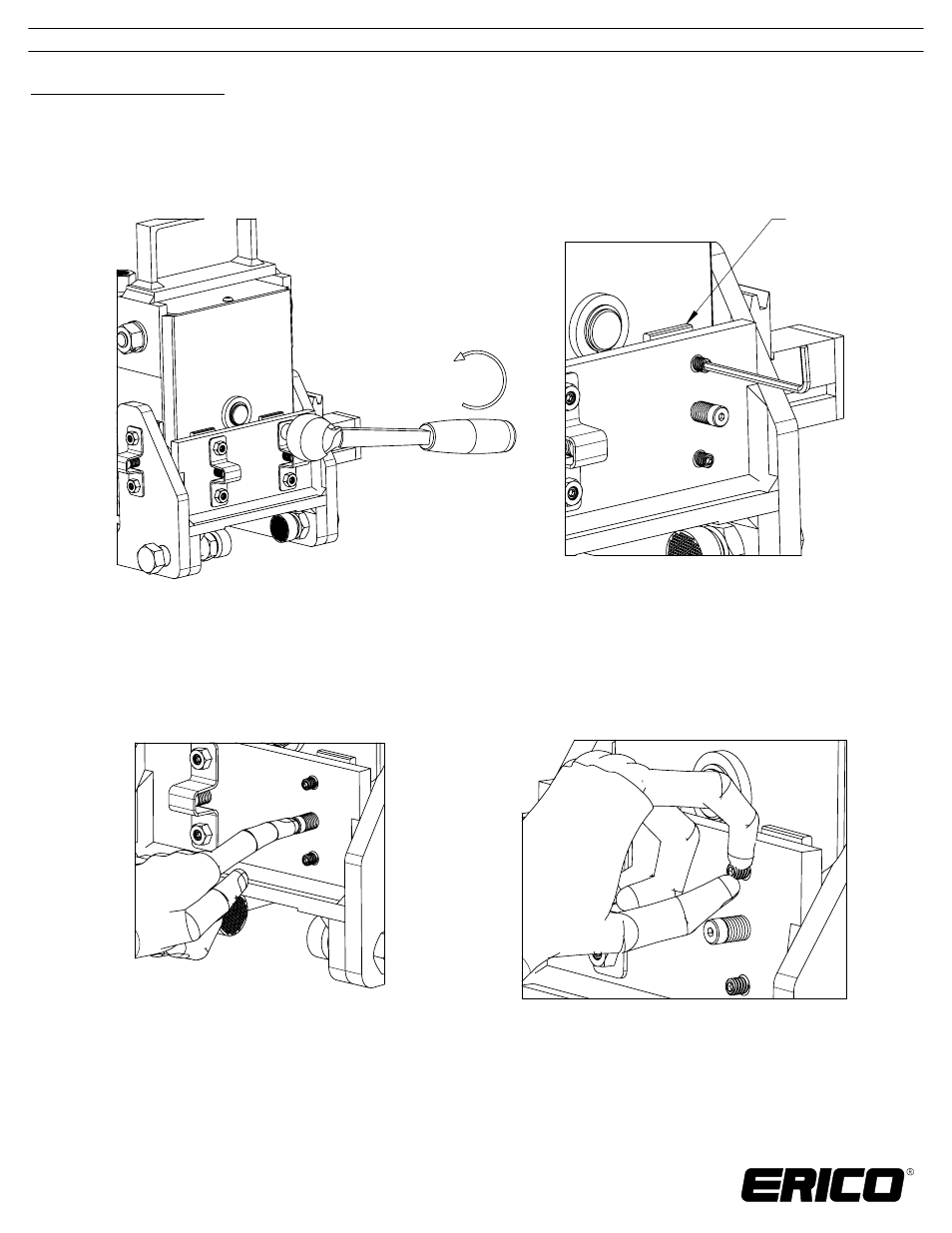
Figure 6 and 7: Removal of lock nuts and loosening of setscrews
Side plate
should pull
away from
gearbox
surface
Side Plate Adjustment:
Attempt to move the gearbox side-to-side and front-to-back within the base assembly. There should
1.
be no noticeable movement relative to the two assemblies. If relative movement is visible, continue
to Step 2.
2. For each side plate, use a 7/16” socket to remove the setscrew lock nuts (Figure 6).
3. Use a 1/8” hex bit to loosen the setscrews, thereby pulling the side plates away from the surface of
the gearbox (Figure 7)
4. Position the gearbox such that the vertical surface opposite the plate being adjusted is flush against
its mating surface on the base assembly. Hold in this position while performing Step 5.
5. Push the head of the side plate spring pin so the side plate is flush against the gearbox (Figure 8).
Use your fingers to tighten both the upper and lower setscrews (Figure 9) to hold the side plate
in place. Be careful not to over tighten because doing so may restrict the vertical movement of
the gearbox.
Figure 8 and 9: Pushing the spring pin while finger tightening screws
6. Repeat Steps 2 through 5 on the remaining side plates until all relative movement is removed.
7. Reinstall the lock nuts on to the setscrews and tighten to 25 in-lbs [2.8 N-m].
TECHNICAL SUPPORT:
www.erico.com
IP8240_B
INSTRUCTION SHEET
4 OF 10
CADDY, CADWELD, CRITEC, ERICO, ERIFLEX, ERITECH, and LENTON are registered trademarks of ERICO International Corporation.
© 2012 ERICO International Corporation.