ElmoMC SimplIQ Digital Servo Drives-Guitar Evaluation Board User Guide User Manual
Page 57
Whistle, Bell Guitar Evaluation Board User Guide
Combined Evaluation Board
MAN-EVLBRD-WHI-BEL-GUI (Ver. 1.401)
57
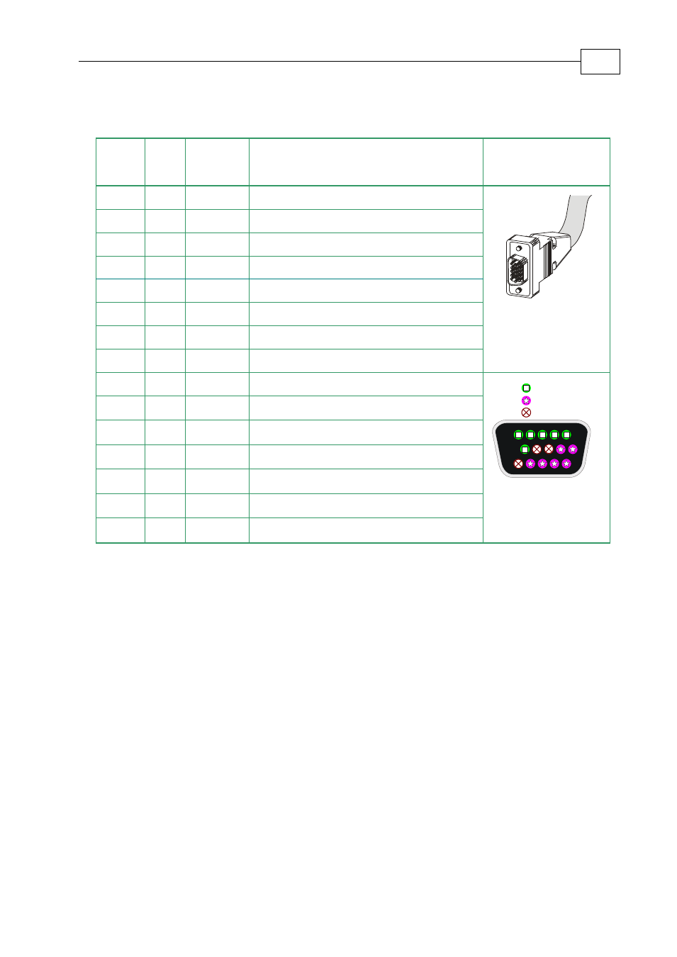
Below are the signals on the Auxiliary Feedback ports when set up to run as a buffered
outputs or emulated outputs of the main encoder (on FEEDBACK A):
Port
Pi
n
Signal
Function
Pin Position
B1
1
CHA
Auxiliary channel A high output
15 Pin high density
D-Sub Plug
B1
2
CHA-
Auxiliary channel A low output
B1
3
CHB
Auxiliary channel B high output
B1
4
CHB-
Auxiliary channel B low output
B1
5
INDEX
Auxiliary index high output
B2
6
CHAO
Buffered channel A output
B2
7
CHAO-
Buffered channel A complement output
PWR
8
+5V
Encoder supply voltage
PWR
9
SUPRET Encoder supply voltage return
5
15
10
1
11
6
Port B1
Port B2
Power
15 Pin high density
D-sub Socket
B1
10
INDEX-
Auxiliary index low output
B2
11
CHBO
Buffered channel B output
B2
12
CHBO-
Buffered channel B complement output
B2
13
INDEXO Buffered index output
B2
14
INDEXO- Buffered index complement output
PWR
15
SUPRET Supply return
Table
2-6: Main Encoder Buffered Outputs or Emulated Encoder Outputs on FEEDBACK B -
Pin Assignments
FEEDBACK B on the “top” of the device being tested has a 15-pin high density D-sub
socket. Connect the Auxiliary Feedback cable, from the controller or other device, to
FEEDBACK B using a 15-pin, high density D-Sub plug with a metal housing. When
assembling the Auxiliary Feedback cable, follow the instructions on page A-1.