ElmoMC SimplIQ Digital Servo Drives-Guitar Evaluation Board User Guide User Manual
Page 61
Whistle, Bell Guitar Evaluation Board User Guide
Combined Evaluation Board
MAN-EVLBRD-WHI-BEL-GUI (Ver. 1.401)
61
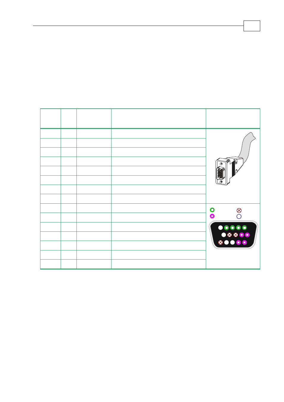
.14.3 Pulse-and-Direction Input Option on
FEEDBACK B
(YA[4]=0)
This mode is used for input of differential pulse-and-direction position commands on Port B1.
In this mode Port B2 provides differential buffered pulse-and-direction outputs for another
axis.
Port
Pi
n
Signal
Function
Pin Position
B1
1
PULS/CHA Pulse/Auxiliary channel A high input
15 Pin D-Sub Plug
B1
2
PULS-/CHA- Pulse-/Auxiliary channel A low input
B1
3
DIR/CHB
Direction/Auxiliary channel B high input
B1
4
DIR-/CHB-
Direction-/Auxiliary channel B low input
5
NC
Do not connect this pin
B2
6
CHAO
Channel A output
B2
7
CHAO-
Channel A complement output
PWR
8
+5V
Encoder supply voltage
PWR
9
SUPRET
Encoder supply voltage return
5
15
10
1
11
6
Port B1
Port B2
Power
N.C.
15 Pin D-Sub Socket
10
NC
Do not connect this pin
B2
11
CHBO
Channel B output.
B2
12
CHBO-
Channel B complement output
13
NC
Do not connect this pin
14
NC
Do not connect this pin
PWR
15
SUPRET
Supply return
Table
2-8: Pulse-and-Direction Auxiliary Encoder Pin Assignment on FEEDBACK B
FEEDBACK B on the “top” of the Evaluation Board has a 15-pin high density D-sub socket.
Connect the Auxiliary Feedback cable from the Pulse and Direction Controller to
FEEDBACK B using a 15-pin, high density D-Sub plug with a metal housing. When
assembling the Auxiliary Feedback cable, follow the instructions in Section B-3.2.