Specifications – Det-Tronics C7052J UV/IR Flame Detector used with R7494, R7495 Controller User Manual
Page 5
requirements, actuation of one or both of two Fire Zone
outputs will also occur. If the controller is programmed
for two separate zones, an output is generated if the
selected number of detectors in the group (one or two)
responds to fire. If an eight detector group is pro-
grammed, the controller energizes both Fire Zone out-
puts if fire is detected by the selected minimum number
(one to four) of detectors.
This voting feature allows different combinations of
detectors to fulfill the logic requirements, and provides
the best balance between dependable fire detection
and freedom from false alarms. Actuation of a Fire Zone
output is signaled by illumination of the appropriate
FIRE ZONE LED on the controller.
Ext Reset/Inhibit
Connecting a switch between terminals 31 and 32
allows the controller to be reset or inhibited from a
remote location (close switch to inhibit/reset).
Fault Detection
The R7495B/C7052J system uses the Automatic oi fea-
ture to continuously check the cleanliness of the detec-
tor viewing windows and sensitivity of the sensors. In
addition, automatic diagnostic circuitry in the controller
monitors the system for wiring continuity faults as well
as other malfunctions that could prevent the system
from responding in the event of a fire. If a fault is
detected:
1. The normally energized Fault relay is de-energized.
This relay is typically used for controlling an exter-
nal fault annunciation device or removing power
from a hazardous process.
2. The FAULT LED on the front panel of the controller
is illuminated to provide a visual indication that a
system fault has occurred.
Field Wiring Connector
The R7495B Controller is furnished with a field wiring
connector backplate that incorporates pressure type
screw terminals for connecting the external wiring. The
use of a Q4004 Mounting Cage is recommended for
mounting the controller. The controller is designed for
installation in a non-hazardous area.
SPECIFICATIONS
SPECTRAL SENSITIVITY RANGE—
UV: The UV sensor responds to radiation over the range
of 0.185 to 0.245 microns (1850 to 2450
angstroms).
IR: The single frequency infrared sensor responds to
radiation between 4.2 and 4.7 microns.
Figure 1 illustrates the spectral response range of the
UV and IR sensors.
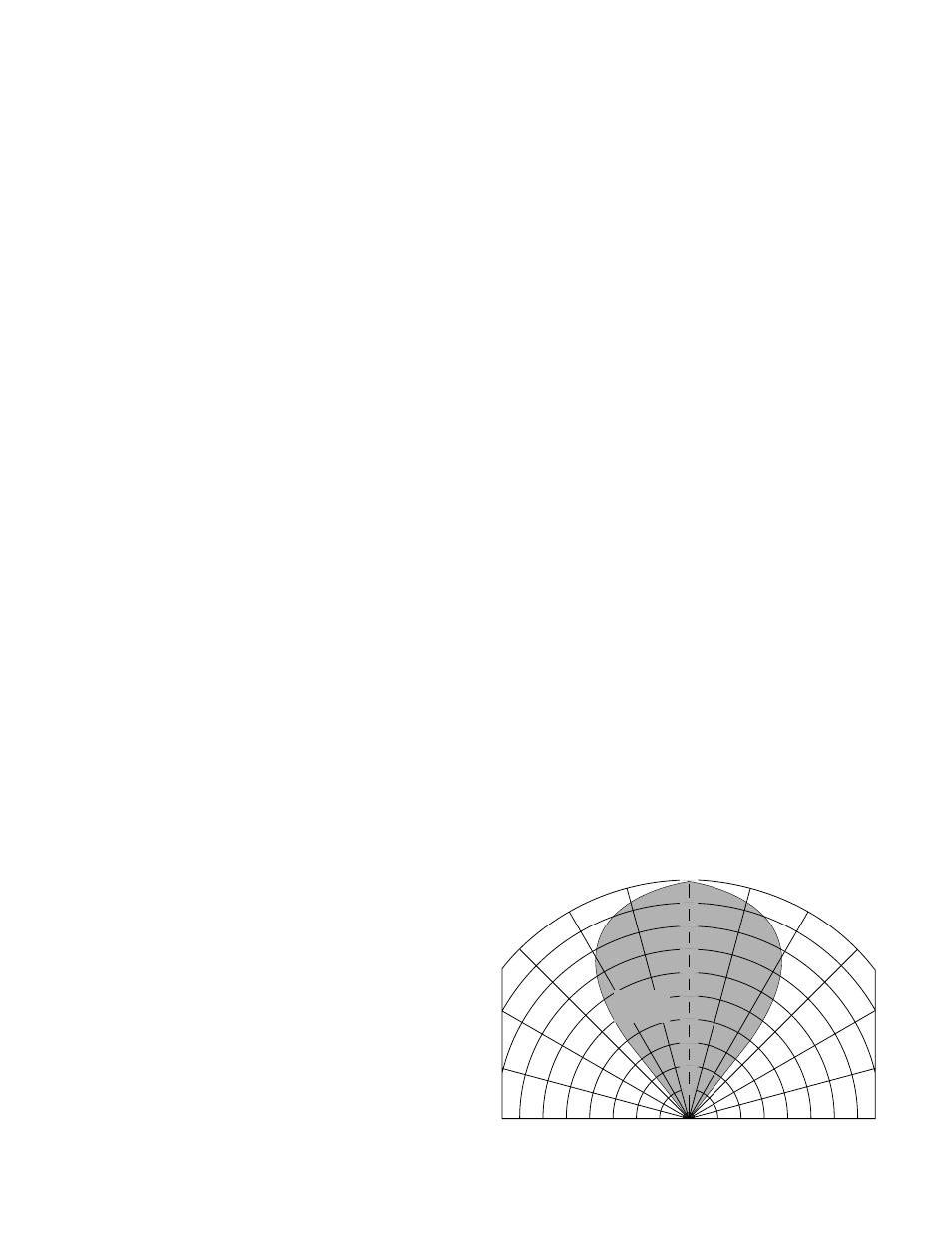
CONE OF VISION—
The C7052J has a 80 degree cone of vision with the
highest sensitivity lying along its central axis. See
Figure 4.
FLAME SENSITIVITY—
The C7052J5 with a part number DE5500 IR Sensor
Module (the sensor part number is printed on its side)
detects a 1 foot by 1 foot gasoline fire at 50 feet, a 2 foot
by 2 foot JP4 fire at 100 feet, and a 10 foot by 10 foot
JP4 fire at 150 feet.
The C7052J with a part number DE3895 IR Sensor
Module (the sensor part number is printed on its side)
detects a 1 foot by 1 foot gasoline fire at 35 to 45 feet, a
2 foot by 2 foot JP4 fire at 100 feet, and a 10 foot by 10
foot JP4 fire at 150 feet.
RESPONSE TIME—
The response time of the detector is a function of fuel,
fire size, distance, orientation of the fire source and the
field programmable controller settings. With typical
controller settings of 0.25 second gate length, 4 counts
per gate, and 4 consecutive gates, the system will
respond to an intense fire signal in less than 2 seconds.
Response times of less than 1 second to an intense fire
signal can be achieved by setting the controller for a
0.125 second gate length, 2 counts per gate, and 3
consecutive gates.
INPUT VOLTAGE—
Controller and Detector
24 vdc nominal (18 vdc minimum, 32 vdc maximum)
with less than 1 volt of ripple.
5
95-8302
0°
15°
30°
45°
15°
30°
45°
A1461
100
90
80
70
60
50
40
30
20
10
DETECTION
DISTANCE
(PERCENT)
100% REPRESENTS THE MAXIMUM DETECTION DISTANCE FOR A
GIVEN FIRE. THE SENSITIVITY INCREASES AS THE ANGLE OF
INCIDENCE DECREASES.
Figure 4—Cone of Vision