Controller installation and wiring – Det-Tronics C7052J UV/IR Flame Detector used with R7494, R7495 Controller User Manual
Page 14
NOTE
The two oi lamps on the DE5500 IR sensor should
be at the top or side of the detector (when viewed
from the front) and the opening on the oi ring
should be at the bottom. See Figure 10. This will
ensure proper operation of the oi system and also
minimize the accumulation of moisture and con-
taminants between the oi ring and the viewing win-
dow. (The oi lamps on the IR sensor are identified
as oblong in shape and clear in color.)
12. Connect the keyed connector plug to the 4-pin con-
nector on the DE5500 IR module. Tuck the lead-
wires inside the module to prevent binding or wire
damage when installing or removing the sensor
housing.
13. Check the O-rings on both sensor housings to be
sure that they are in good condition and are fitted
properly, then re-install the sensor housings on the
junction box cover. (See the “Maintenance” section
of this manual for information regarding care of O-
rings.) The sensor housing with the large viewing
window is for the UV detector and the sensor hous-
ing with the small window is for the IR detector.
Hand tighten the sensor housings into the base until
the O-rings are fully seated to maintain the explo-
sion-proof and watertight integrity of the housing. If
the unit is equipped with cover locking clamps,
loosen the clamps sufficiently so that the clamp
catches can be seated in the blind holes on the
junction box cover. Fasten the clamps securely
using a 5/32 inch hexagonal (Allen) wrench. (See
Figure 15.)
14. Re-install the junction box cover, making sure that
the center nine-pin connector on the cover is prop-
erly aligned with the connector in the junction box.
The six screws must be tight to ensure a metal to
metal fit to maintain explosion-proof and watertight
integrity of the junction box.
15. Inspect and clean (if necessary) the detector view-
ing windows and
oi rings by following the instruc-
tions in the “Maintenance” section of this manual.
16. The opening of the
oi rings should be pointed down
to minimize the accumulation of moisture or con-
taminants behind the ring (see Figure 10). Verify
that the
oi test lamp is at the top or side of each
sensor. Note that Figure 10 shows the DE5500 IR
module with the test lamps located together on one
side of the edge. The DE3895 IR module has test
lamps located directly opposite one another. In
both cases, ensure that no test lamp is positioned
at the bottom when the detector is installed.
17. If the detector is so equipped, install the air shields
on each sensor housing, then connect the air sup-
ply line to the air shields.
NOTE
Be sure that the detector is correctly aimed at the
potential hazard and that no obstructions interfere
with its line of vision. In addition, UV and/or IR
absorbing gases (see Table 2) should not exist
between the detector and the potential hazard.
CONTROLLER INSTALLATION
AND WIRING
The R7495B Controller must be mounted in a non-haz-
ardous area. The optional Q4004 Mounting Cage is
designed to hold up to eight modules in a 19 inch
instrument rack. Other mounting cages are available to
accommodate 1, 2, 3, 4 or 6 units. These mounting
14
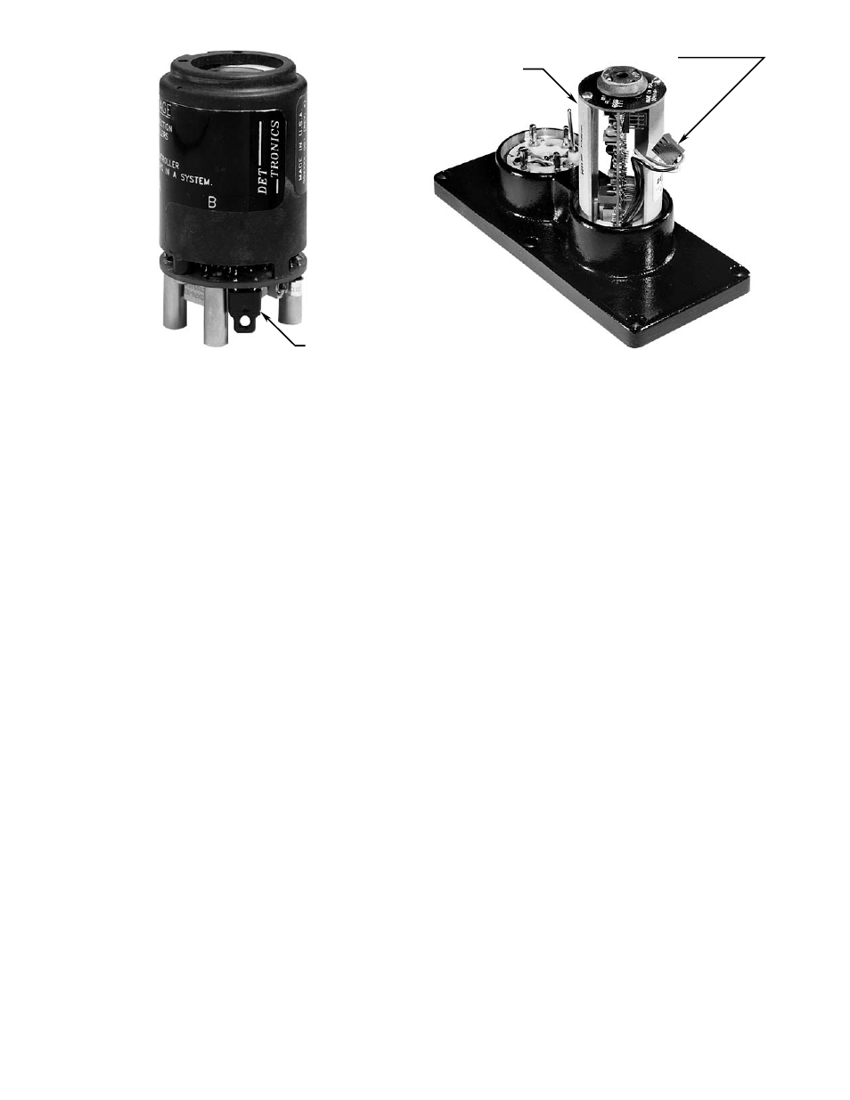
A1331
IR MODULE
4–WIRE CONNECTOR PLUG
Figure 17—IR Module with Four-Wire Connector
JUMPER "J"
A1702
Figure 16—Jumper Plug