Det-Tronics C7052J UV/IR Flame Detector used with R7494, R7495 Controller User Manual
Page 15
cages can also house voltage converters and other
micro-module equipment that is used in conjunction
with the R7495B Controller as part of the total protection
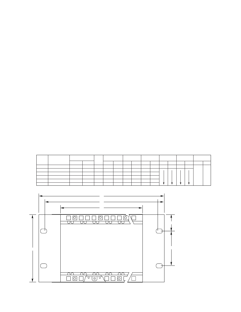
system. See Figure 18 for illustration and dimensions.
Electrical Connections
All electrical connections are made to the field wiring
connector that is furnished with the controller. Figure 19
shows the terminal configuration for the controller. Power
to the R7495B Controller and C7052J Detectors may be
furnished by external 24 volt batteries, a regulated dc
power supply, or optional Det-Tronics voltage converters.
Terminal 1 —
Connect to the positive (+)
side of an external 24 vdc
power source.
Terminal 2 —
Connect to the negative (–)
side of the dc power source
(circuit ground). The C termi-
nals on the detectors must also
be connected to circuit
ground.
Terminal 3 —
Do not use.
Terminal 4 —
Do not use.
Terminal 5 —
Chassis (earth) ground termi-
nal is connected to the con-
troller chassis and should be
connected to the nearest earth
ground connection.
Terminals 6 to 11 —
Relay Contacts, Fire Zone 1.
Terminals 12 to 17 —
Relay Contacts, Fire Zone 2.
Terminals 18 to 20 —
Relay Contacts, Alarm 1.
Terminals 21 to 23 —
Relay Contacts, Alarm 2.
Terminals 24 to 26 —
Fault relay contacts- the fault
relay is normally energized in
the Normal mode with no sys-
tem faults present.
Terminals 31 and 32 — External Reset - a normally
open switch connected
between terminals 31 and 32
(circuit ground) allows the con-
troller to be reset from a
remote location.
Terminal 33 —
Circuit ground - connect to all
detector wiring shields.
15
95-8302
(A)
(B)
(C)
1.48 (37.59)
(D)
A1475
ALL CONTROLLER CAGES REQUIRE
A MINIMUM OF 10.12 INCHES (257.1 MM)
DEPTH CLEARANCE
(E)
RACK
PART NUMBER
CONTROLLER
TYPE
005269-XXX
POSITIONS FOR:
HT:
DIM. (A)
DIM. (B)
DIM. (C)
DIM. (D)
DIM. (E)
WEIGHT
FIRE GAS
INCH MM
INCH MM
INCH MM
INCH MM
INCH MM
LB
KG
4U
–001
8
16
4U
19.00
482.6
18.30
464.8
17.36
440.9
4.00
101.6
6.97
177.1
9.3
4.2
4U
–002
6
12
4U
15.06
382.6
14.36
364.7
13.42
340.9
7.6
3.5
4U
–003
4
8
4U
11.13
282.6
10.43
264.9
9.49
241.1
5.9
2.7
4U
–004
3
6
4U
9.16
232.7
8.46
214.9
7.52
191.0
5.1
2.3
4U
–005
2
4
4U
7.19
182.7
6.49
164.9
5.55
141.0
4.2
1.9
4U
–006
1
2
4U
5.22
132.6
4.52
114.8
3.58
90.9
3.1
1.4
Figure 18—Q4004 Mounting Cage Dimensions in Inches (MM)