Det-Tronics C7052J UV/IR Flame Detector used with R7494, R7495 Controller User Manual
Page 13
13
95-8302
0.47
µ
f
1
2
3
4
5
6
7
8
9
10
11
12
13
14
15
16
17
18
19
20
21
22
23
24
25
26
31
32
33
34
35
36
37
38
39
40
41
42
43
44
45
46
47
48
49
50
+
–
CHASSIS (EARTH) GROUND
NC
NO
COM
NC
NO
COM
NC
NO
COM
NC
NO
COM
NC
NO
COM
NC
NO
COM
NC
NO
COM
EXTERNAL RESET
CIRCUIT GROUND
CIRCUIT GROUND
D1
D2
D3
D4
D5
D6
D7
D8
B1
B2
B3
B4
B5
B6
B7
B8
A
B
C
D
A
B
C
D
A
B
C
D
FAULT*
ALARM 1
ALARM 2
FIRE ZONE 2
FIRE ZONE 1
DC INPUT
THE FAULT RELAY, SHOWN DE-ENERGIZED,
IS ENERGIZED UNDER NORMAL OPERATING CONDITIONS.
*
UP TO EIGHT DETECTORS CAN BE CONNECTED
*
A0976
R7495
C7052J
C7052J
C7052J
LOAD
LOAD
PROCESS
CONTROL
FAULT
ALARM
HOT
NEUTRAL
EXTERNAL
RESET SWITCH
–
24 VDC
+
IMPORTANT
If the UV sensor module is supplied with a jumper
plug “J” as shown in Figure 16, remove the jumper
plug from the detector tube module and discard it.
Jumper plug “J” is supplied for installations in
which the tube module is used with other detector
models.
NOTE
The C7052J contains semiconductor devices that
are susceptible to damage by electrostatic dis-
charge. An electrostatic charge can build up on
the skin and discharge when an object is touched.
Therefore, use caution when handling the detector,
taking care not to touch the terminals or electronic
components. For more information on proper han-
dling, refer to Service Memo form 75-1005 at the
front of this manual.
9.
If the IR sensor is already installed, proceed to step
12. If the IR sensor is not installed, remove the IR
module from its shipping package (avoid touching
the IR sensing element at the top of the module).
Two IR sensor designs exist; the DE5500 is electri-
cally connected via a wire harness on the junction
box that must be threaded through the sensor mod-
ule to a connector at the top of the module (see
Figure 17), the DE3895 plugs directly onto a termi-
nal block in the base of the IR housing via connec-
tors on the bottom of the IR sensor module (see
Figure 12).
10. If the IR sensors are the DE3895 type that electri-
cally connects directly onto the terminal block,
install them by lining up the connection pins using
the index pin to properly orient the module. Press
the sensor firmly into place.
11. If the IR sensor is the DE5500 type that connects
via a wire harness (Figure 17), thread the wire leads
and keyed connector plug through the slotted
opening on the side of the IR module. Plug the IR
module into the two banana plugs inside the junc-
tion box cover. If repositioning is necessary to
properly align the
oi lamps (as described in the
“NOTE” below), this module can be rotated 180°
and remounted on the banana plugs.
Figure 14—Typical Application Wiring
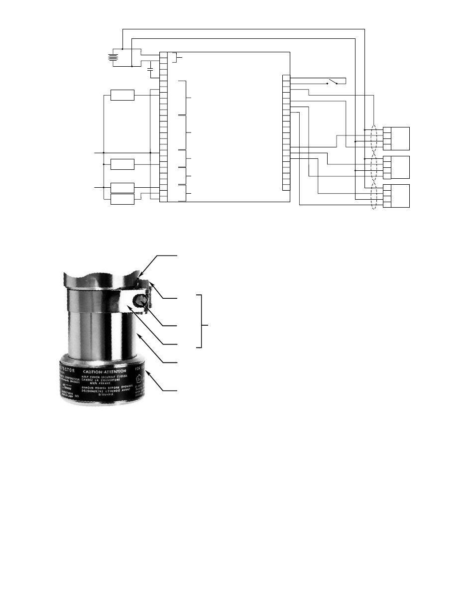
BLIND HOLE
COVER
LOCKING
ASSEMBLY
CATCH
CLAMP
SCREW
STRAP
BARREL
LENS CAP
A1078
Figure 15—Cover Locking Assembly (Optional)