Det-Tronics C7052J UV/IR Flame Detector used with R7494, R7495 Controller User Manual
Page 17
The rocker switches must be set before power is
applied to the system. Do not plug the controller in or
remove it from the mounting rack while power is turned
on.
CAUTION
Use care when setting the rocker switches on the
controller. An incorrectly set rocker switch can
result in an obvious controller malfunction, or the
controller could appear to be functioning normally,
but not produce the desired output in response to
the input conditions. (Some of the rocker switches
on the R7495B are not used. These rockers
should be left open.)
Detector Selection - Rocker Switches 1-1 to 1-8
The number after the dash corresponds to the number
of each zone. Open the rocker for each zone that has a
detector connected to it. Care must be taken when set-
ting these rockers. If a rocker is set open, but no detec-
tor is connected in that location, the controller will indi-
cate a fault. If a rocker is set closed when a detector is
connected, the controller will appear to be operating
correctly and will produce an alarm condition if the cor-
responding detectors sense a fire. However, that
detector will be eliminated from the Automatic
oi test
sequence, and any faults occurring in its circuitry or
wiring will not be indicated.
STAR Logic Programming (System Sensitivity and
Time Delay) - Rocker Switches 2-1 to 2-8 (Gate
Length), Rocker Switches 3-1 to 3-4 (Count
Selection Per Gate), and Rocker Switches 3-5 to 3-
8 (Consecutive Gates Selection).
The STAR Logic switch settings determine system sen-
sitivity and time delay. The most important factor in
determining the appropriate sensitivity setting for a par-
ticular application is the intensity of radiation expected
to reach the detector in the event of a fire. This
depends on several factors, including the distance of
the detector from the potential fire, the fuel type, the
flame size, and whether any radiation absorbing vapors
are present (these are listed in Table 2).
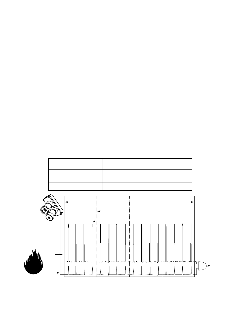
The most effective way to set system sensitivity is to
install the system, program the STAR Logic according
to the typical settings shown in Figure 21, program all
other aspects of controller operation according to this
section (“Programming the Controller”), then perform
the “Initial and Periodic Checkout Procedure” using a
UV/IR test lamp and the “STAR Programming Checkout
Procedure.”. If the system fails to respond appropriate-
ly during these tests and all system wiring is correct,
then system sensitivity (gate length, counts per gate,
and consecutive gates) needs to be adjusted. It is
important that all wiring and programmed settings be
checked to ensure that they are correct before adjusting
these settings.
17
95-8302
UV SIGNAL
FLAME
C7052
UV/IR
FIRE
ALARM
CONDITION
COUNT (SIGNAL)
4 COUNTS PER GATE
4 CONSECUTIVE GATES
0.25 SECOND GATE LENGTH
A1584
UV
AND
IR
IR SIGNAL
Figure 21—Graphic Representation of STAR Logic (Typical Setting Shown)
R7495 STAR Logic Program
4 Counts per Gate
0.25 Second Gate Length
4 Consecutive Gates
R7495 Switch Settings
Rockers Closed
Rockers Open
3-3
3-1, 3-2, 3-4
2-4
2-1, 2-2, 2-3, 2-5, 2-6, 2-7, 2-8
3-7
3-5, 3-6, 3-8