Det-Tronics C7052J UV/IR Flame Detector used with R7494, R7495 Controller User Manual
Page 3
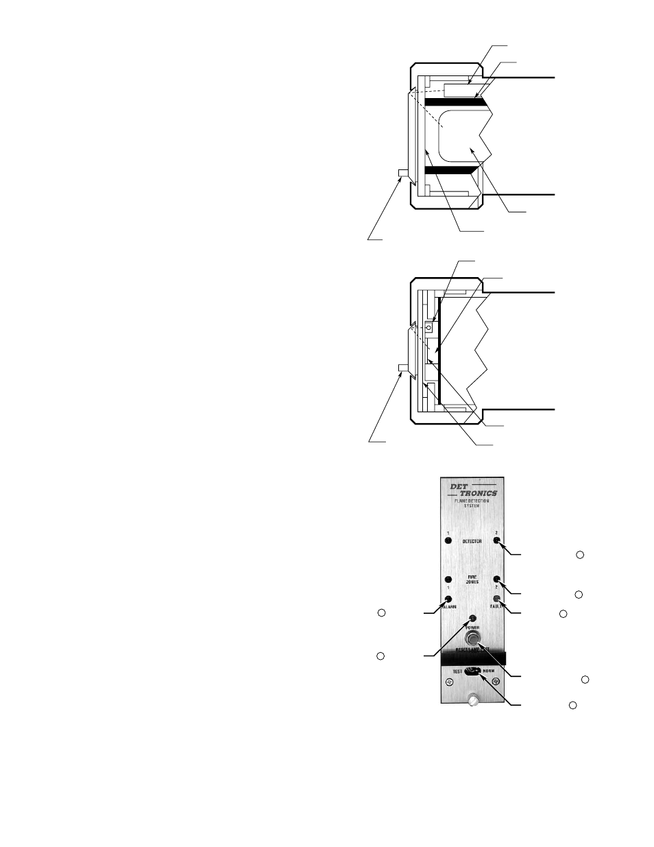
lamps, as shown in Figure 2. Although the test lamps
are mounted in the same enclosure with the sensor, an
optical shield prevents the test beam from reaching the
sensor directly. The test beam travels out through the
viewing window, where it encounters the reflective
oi
ring and is directed back through the window to the
sensor. Electronic circuitry in the detector then evalu-
ates the return signal from the sensor and generates the
appropriate output response. Since the test beam must
pass through the same portion of the viewing window as
radiation produced by a fire, this test of the ability of the
detector to “see” a flame has a high degree of reliability.
Detector Enclosure
The C7052J features an explosion-proof, dust-tight, and
water-tight (NEMA 4/IP66) housing that is designed for
installation in hazardous locations in both indoor and
outdoor environments. The enclosure is FM approved,
CSA certified, and BASEEFA/CENELEC approved.
Controller
The R7495B is designed for use with 24 volt dc power
supplies, but will operate from any direct current supply
between 18 and 32 volts. The unit will tolerate tran-
sients such as those that can occur when fully dis-
charged batteries are placed on charge. When power
is present at the R7495B Controller, it is indicated by a
continuously energized green LED. All other lights and
displays on the R7495B front panel are normally off, but
may be periodically checked for operation by pressing
the RESET/LAMP TEST button located directly below the
POWER light as illustrated in Figure 3. It is not neces-
sary for the controller to be in the TEST mode when this
check is performed.
With power applied and the TEST/NORM toggle switch
in the normal mode, the R7495B Controller continuously
cycles through the Automatic Optical Integrity test (see
the “
oi Feature” section), checking each detector and
its wiring. At the same time, it monitors the system for
any status changes, such as a fault, a “fire” signal from
one of the detectors or zones, or a change in the setting
of the TEST/NORM toggle switch. If a status change
occurs, the controller will respond accordingly by indi-
cating the change on the front panel LEDs and generat-
ing the appropriate output.
Front Panel
The front panel of the R7495B provides switches for
selecting mode of operation and resetting the controller.
It also provides LEDs for indicating system status infor-
mation. Figure 3 illustrates the front panel of the con-
troller.
3
95-8302
UV DETECTOR
IR DETECTOR
UV TEST LAMP
OPTICAL SHIELD
VIEWING WINDOW
SNAP-IN
oi
RING
IR TEST LAMP (2)
IR SENSING ELEMENT
SNAP-IN
oi
RING
OPTICAL FILTER
VIEWING WINDOW
UV SENSOR
B1048
Figure 2—oi Function within th e Detector
MODE SWITCH
RESET/LAMP TEST
PUSHBUTTON
FAULT LED
FIRE ZONE LEDS
DETECTOR LEDS
POWER LED
ALARM LED
A1703
1
2
3
5
6
7
4
Figure 3—R7495B Controller Front Panel