Typical system application, Figure 23—system layout chart 20 – Det-Tronics C7052J UV/IR Flame Detector used with R7494, R7495 Controller User Manual
Page 20
Common— For up to eight channels voting, and Fire
Zone outputs 1 and 2 energized simultaneously:
4-1 is open
4-2, 4-3, 4-4 - All open = any one detector
Any one closed = any two detectors
Any two closed = any three detectors
All three closed = any four detectors
Outputs Latching/Non-latching - Rocker Switch 4-5
Once energized, an output will remain on (latching) until
the controller is reset if rocker 4-5 is set open.
Rockers 4-6, 4-7 and 4-8 are not used.
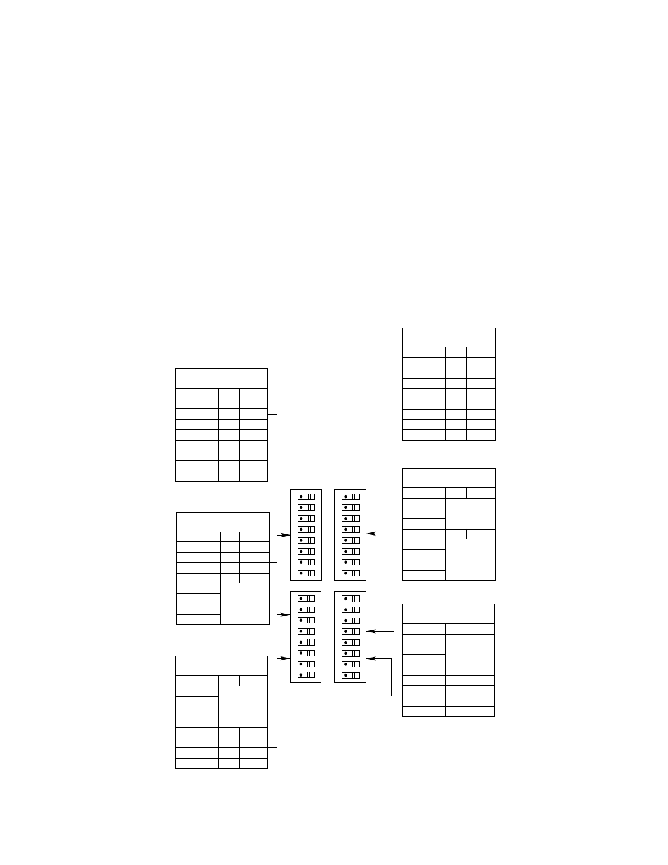
When the proper position for each of the rocker switch-
es has been determined, record this information careful-
ly on the system layout chart in Figure 23. This provides
a means of double checking switch positions before
power is applied to the controller, and to provide a
record of switch positions for future reference.
TYPICAL SYSTEM APPLICATION
The following application is an example only. For assis-
tance in adapting a system to your individual require-
ments, contact the Field Support Group at Detector
Electronics.
Power is supplied to the system by a 24 volt dc power
supply. A four conductor shielded cable is used to con-
nect the detectors to the controller as shown in Figure
14. Terminals A and C (power connections) are com-
mon to all the detectors in the system. The B- and D-
leads of each detector are connected to their corre-
sponding “B” and “D” terminals on the controller. The
shields are tied together and grounded at terminal 33.
A 0.47 microfarad, 250 volt capacitor is placed between
terminal 5 and terminal 2. A remote reset switch is pro-
vided for resetting the controller or inhibiting the outputs
from a remote location. The connections are made to
terminals 31 and 32.
SWITCH 1
DETECTOR SELECT
SWITCH 3
CONSECUTIVE GATE
SELECTION
SWITCH 3
COUNT SELECTION
SWITCH 2
GATE LENGTH (SECONDS)
SWITCH 4
OUTPUTS LATCHING
SWITCH 4
VOTING LOGIC
ROCKER
OPEN CLOSED
ROCKER
OPEN CLOSED
ROCKER
OPEN CLOSED
ROCKER
OPEN CLOSED
ROCKER
OPEN CLOSED
ROCKER
OPEN CLOSED
1
2
3
4
5
6
7
8
1
2
3
4
5 – 1 GATE
6 – 2 GATES
7 – 4 GATES
8 – 8 GATES
1 (1 COUNT)
2 (2 COUNTS)
3 (4 COUNTS)
4 (8 COUNTS)
5
6
7
8
1
2
3
4
5
6
7
8
1
2
3
4
5
6
7
8
8 – 4.0
7 – 2.0
6 – 1.0
5 – 0.5
4 – 0.25
3 – 0.125
2 – 0.062
1 – 0.031
1
2
3
4
5
6
7
8
OPEN SWITCH FOR EACH
DETECTOR CONNECTED
ADD VALUE OF CLOSED
ROCKERS – 2 GATES MINIMUM
ADD VALUE OF CLOSED
ROCKERS – 2 COUNTS MINIMUM
– USE MULTIPLICATION FACTOR
IF GATE IS 0.5 SECOND OR GREATER
ADD VALUE OF
CLOSED ROCKERS
OPEN = LATCHING
SEE VOTING TABLE IN FIGURE 20
OPEN
A0975
1
2
3
4
5
6
7
8
OPEN
1
2
3
4
5
6
7
8
OPEN
1
2
3
4
5
6
7
8
OPEN
OPEN
OPEN
A0975
Figure 23—System Layout Chart
20