Det-Tronics C7052J UV/IR Flame Detector used with R7494, R7495 Controller User Manual
Page 19
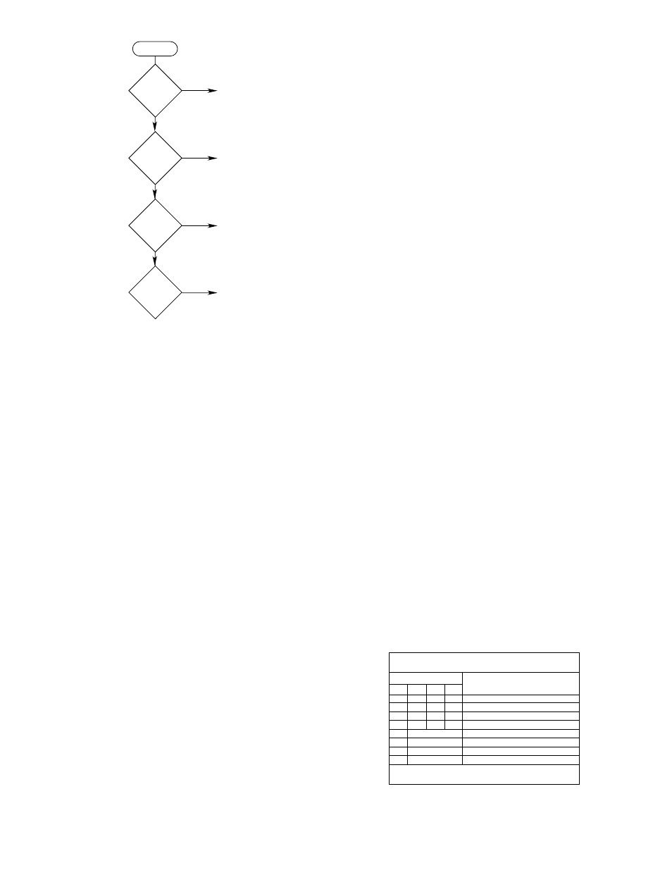
from Figure 22. In this case, 4 counts per gate is multi-
plied by a factor of 4, to obtain a total programmed
value of 16 counts per gate. Without this feature, it
would be possible to program the system to interpret 4
counts in 1.5 seconds as a fire signal, which would
make the system susceptible to frequent false alarms.
Consecutive Gate Selection - Rocker Switches 3-5
to 3-8
These rockers select the number of consecutive gates
required for a fire signal. Consecutive gates are
selectable in 1-gate increments from 2 to 15 gates. If
fewer than 2 gates are selected (only rocker 5 closed),
the microprocessor will select 2. The values of the rock-
ers closed are added together. The typical consecutive
gate settings used in most applications are between 3
and 8 gates.
Rocker 3-5 - 1 Gate
Rocker 3-6 - 2 Gates
Rocker 3-7 - 4 Gates
Rocker 3-8 - 8 Gates
Detector Grouping/Voting Logic Selection 4-1 to 4-4
Rocker switches 4-1 to 4-4 are used to program the
controller for the particular voting arrangement to be
used. (Refer to the “System Description” section of this
manual for a description of the options available with the
Detector Grouping/Voting Logic feature.) Refer to
Figure 20 (Switch Assembly 4) to determine the correct
positions for rocker switches 4-1 to 4-4.
NOTE
When in the Normal mode and the outputs are set
for non-latching operation, the voting process will
actuate the Fire Logic output(s) only if the pre-
selected number of detectors “see” fire at the same
time. When the outputs are set for latching opera-
tion, the voting process will actuate the Fire Logic
output(s) when voting criteria have been met, even
if a fire is not being seen by each detector at the
same time.
Detector Grouping - Rocker 4-1
Separate - closed
Combined - open
When rocker switch 4-1 is closed, detectors 1 to 4 acti-
vate the Alarm 1 and Fire Zone 1 outputs, and detectors
5 to 8 activate the Alarm 2 and Fire Zone 2 outputs.
When rocker switch 4-1 is open, a fire at any of eight
detectors causes actuation of both Alarm outputs.
Fulfillment of the programmed voting requirements
results in actuation of both Fire Zone outputs.
Voting Selection - Rockers 4-2 to 4-4
Rocker switches 4-2 to 4-4 are used to program the
controller for the particular voting logic arrangement to
be used. Refer to the “Description” section of this man-
ual for a description of the options available with the vot-
ing logic feature. Then refer to the Voting Selection
Table (Table 3) to determine the correct switch posi-
tions.
Separate — For two separate voting groups:
4-1 is closed
4-2 is not used in this voting arrangement
4-3 programs Fire Zone output 2 (channels 5, 6, 7, 8)
- open, any one detector
- closed, any two detectors
4-4 programs Fire Zone output 1 (channels 1, 2, 3, 4)
- open, any one detector
- closed, any two detectors
19
95-8302
START
ROCKER 2–8
CLOSED?
ROCKER 2–7
CLOSED?
ROCKER 2–6
CLOSED?
ROCKER 2–5
CLOSED?
YES
YES
YES
YES
MULTIPLY BY 16
MULTIPLY BY 8
MULTIPLY BY 4
MULTIPLY BY 2
A974
NO
NO
NO
Figure 22—Multiplication Factors
Table 3—Voting Selection Table
SWITCH ASSEMBLY 4
VOTING LOGIC
OP = OPEN, CL = CLOSED, DC = DON'T CARE
1•2 = 1 AND 2
4-1
CL
CL
CL
CL
OP
OP
OP
OP
4-2
DC
DC
DC
DC
4-3
DC
DC
OP
CL
4-4
OP
CL
DC
DC
DETECTOR RESPONSE
ROCKER POSITION
1
1
2
2
1•2
1•2
1•2
1•2
FIRE
ZONE
OUTPUTS
1 DETECTOR
2 DETECTORS
1 DETECTOR
2 DETECTORS
1 OF 8 DETECTORS
2 OF 8 DETECTORS
3 OF 8 DETECTORS
4 OF 8 DETECTORS
ALL OPEN
1 CLOSED
2 CLOSED
3 CLOSED