Features, System description – Det-Tronics C7052J UV/IR Flame Detector used with R7494, R7495 Controller User Manual
Page 2
2
FEATURES
• Controller continuously monitors up to eight detec-
tors.
• Detectors can be divided into either two groups of
up to four detectors, each with its own alarm and
fire zone output, or one group of up to eight detec-
tors with two alarm and two fire zone outputs.
• Two fire zone relays, two alarm relays and a fault
relay provided.
• Ignores false alarm sources such as arc welding, x-
rays, gamma radiation and radiation from flickering
hot objects.
• Fast response - typically 1 to 5 seconds for an
intense hydrocarbon fire.
• Field adjustable sensitivity and time delay.
• Front panel LEDs indicate fire response and fault
conditions.
• Microprocessor control provides continuous diag-
nostics and automatic fault indication.
• Automatic Optical Integrity (
oi
) for both UV and IR
sensors.
• Explosion-proof (flame-proof) detector housing
• FM approved, CSA and BASEEFA/CENELEC certi-
fied.
• Voting circuitry for improved false alarm rejection.
SYSTEM DESCRIPTION
Detector
The C7052J UV/IR Flame Detector is an explosion-proof
device that consists of a UV sensor and an IR sensor
mounted side-by-side on a junction box. This mounting
arrangement allows both sensors to monitor the same
hazardous location with a 80 degree cone of vision. Up
to eight C7052J Detectors can be connected to one
R7495B Controller.
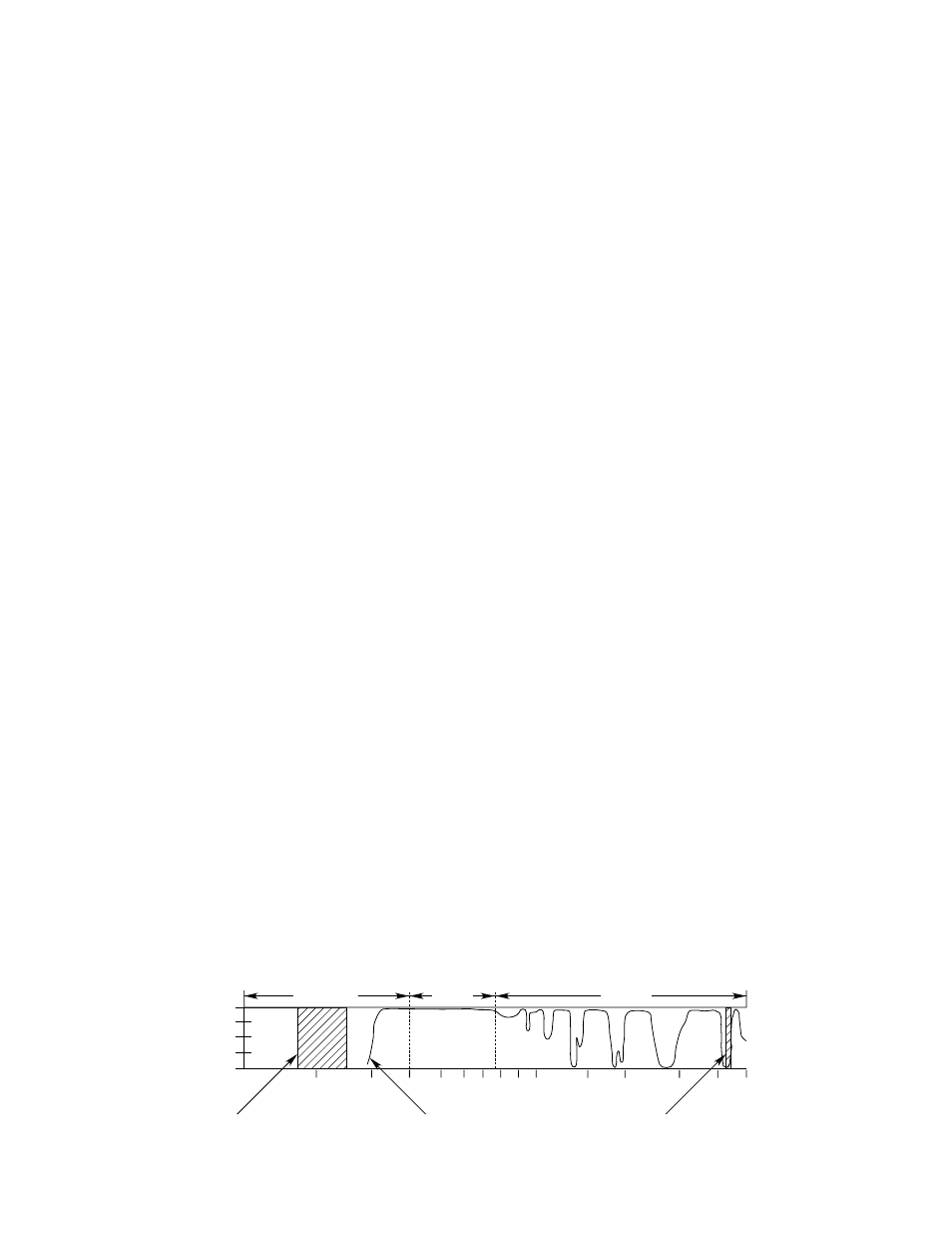
The UV sensor responds to high energy radiation with
wavelengths from .185 to .245 microns (1850 to 2450
angstroms). See Figure 1. It detects radiation from
sources such as fire, arc welding, lightning, x-rays and
gamma rays. However, it is not sensitive to radiation
from the sun or radiation from flickering hot objects
(blackbodies).
The IR sensor is sensitive to IR radiation over the range
of 4.2 to 4.7 microns. See Figure 1. It is not sensitive to
radiation from the sun, lightning, x-rays, gamma rays, or
arc welding. However, it will respond to fire and flicker-
ing blackbody (heat) radiation sources. IR radiation that
is generated by a hydrocarbon flame which reaches the
detector in pulsations or “flicker.” These pulsations are
present in all flames and are created by turbulent mix-
ing of fuel with air. For this reason, electronic circuitry in
the detector monitors the output of the IR sensing ele-
ment for the appropriate amplitude and a flicker fre-
quency between 1 and 16 cycles per second. If both
the radiation and flicker requirements are met, a fire sig-
nal is generated. This dual criteria for the IR detector
results in increased reliability. However, since the IR
detector responds only to hydrocarbon fires, the UV/IR
detector cannot respond to non-hydrocarbon fires such
as burning hydrogen, ammonia or metal.
The detector junction box contains a +290 vdc power
supply for the UV sensor as well as circuitry to process
signals from both sensors. When both sensors detect a
fire, the IR sensor activates the circuitry in the junction
box to allow the signal from the UV sensor to be sent to
the controller. By using both a UV and an IR sensor, the
C7052J is able to discriminate virtually all false alarm
sources from a true hydrocarbon fire.
oi Feature
Both sensors are equipped with the automatic Optical
Integrity (
oi) test feature. This patented system assures
proper operation of the detector by checking the clean-
liness of the optical surfaces, sensitivity of the sensors,
and proper functioning of the electronic components of
the detector once every minute. If a problem should
occur, it is quickly detected. The
oi test is accom-
plished without the use of an external UV or IR source.
To minimize the possibility of nuisance fault signals, the
detector must fail the automatic
oi test three consecu-
tive times for an
oi fault signal to be generated.
The
oi test is initiated by a signal from the controller
which causes actuation of the
oi test lamps. A calibrat-
ed low level test beam is generated by the
oi test
5.0
4.0
3.0
2.0
1.5
1.0
0.9
0.8
0.7
0.6
0.5
0.4
0.3
0.2
0.1
ATMOSPHERIC
TRANSMISSION
WAVELENGTH (MICRONS)
SOLAR RADIATION REACHING THE EARTH
VISIBLE
INFRARED
ULTRAVIOLET SENSOR RESPONSE
ULTRAVIOLET
100
75
50
25
0
A1516
INFRARED SENSOR RESPONSE
Figure 1—Detector Sensitivity Range