Det-Tronics C7052J UV/IR Flame Detector used with R7494, R7495 Controller User Manual
Page 11
NOTE
The wiring procedures in this manual are intended
to ensure proper functioning of the device under
normal conditions. However, because of the many
variations in wiring codes and regulations, total
compliance to these ordinances cannot be guaran-
teed. Be certain that all wiring complies with appli-
cable regulations that relate to the installation of
electrical equipment in a hazardous area. If in
doubt, consult a qualified electrician before wiring
the system.
2. Remove the junction box cover assembly from the
base by loosening the six screws on the cover (see
Figure 12).
3.
Mount the detector junction box base and mounting
bracket assembly on the wall or ceiling. See
Figures 7 and 8 for dimensions of the mounting
bracket. The mounting surface should be free of
excessive heat and vibration.
NOTE
Do not wire the system, or plug in or remove the
sensor modules with power applied.
4. Figure 13 shows the detector terminal block. Letter
designations correspond to connections as indicat-
ed below.
A = +24 vdc
B = detector output signal
C = circuit ground
D = Oi control signal
Minimum requirements for wiring the detector are
for the B-lead (signal) to be shielded. It is preferred
that the A-lead, C-lead, and D-lead also be shield-
ed to provide maximum immunity to EMI/RFI. The
wiring procedure below is the preferred method of
detector to controller wiring. Refer to Figure 14 for
an example of a typical application showing detec-
tor to controller wiring.
a. Connect the B-lead shields to the chassis
(earth) ground connection (terminal 5) of the
controller.
b. Be certain that the shield is NOT connected
to the detector at terminal “C” (circuit ground)
or any other points.
c. Connect the C-leads of the detectors to termi-
nal 2 (circuit ground) of the controller.
d. Connect a non-polarized 0.47 microfarad 250
vdc capacitor from terminal 5 to terminal 2.
This places the earth ground and the circuit
ground at the same ac potential, minimizing
induction of noise into the system through the
detector cable.
5.
Check to make sure that all wiring is correct. If con-
duit is used, pour the conduit seals and allow them
to dry.
6. If the UV and/or IR sensor modules are already
installed in the detector housing, proceed to step
12. If the sensors are not installed, remove the
applicable sensor housings from the junction box
cover (see Figure 12). If the detectors are
equipped with a cover locking device (see Figure
15), loosen the clamp and disengage the “catch”
from the blind hole. The tool required is a 5/32-inch
hexagonal (Allen) wrench.
7.
If the UV sensor module is already installed, proceed
to step 9. If the UV module is not installed, remove
the UV sensor module from its shipping package.
8.
Determine the proper orientation for the UV module
by lining up the long index pin on the terminal block
with the hole in the printed circuit board of the mod-
ule. See Figure 12. Firmly press the module into
place on the terminal block, taking care not to touch
the glass envelope of the sensor module, since fin-
gerprints can absorb UV radiation and reduce the
sensitivity of the sensor.
11
95-8302
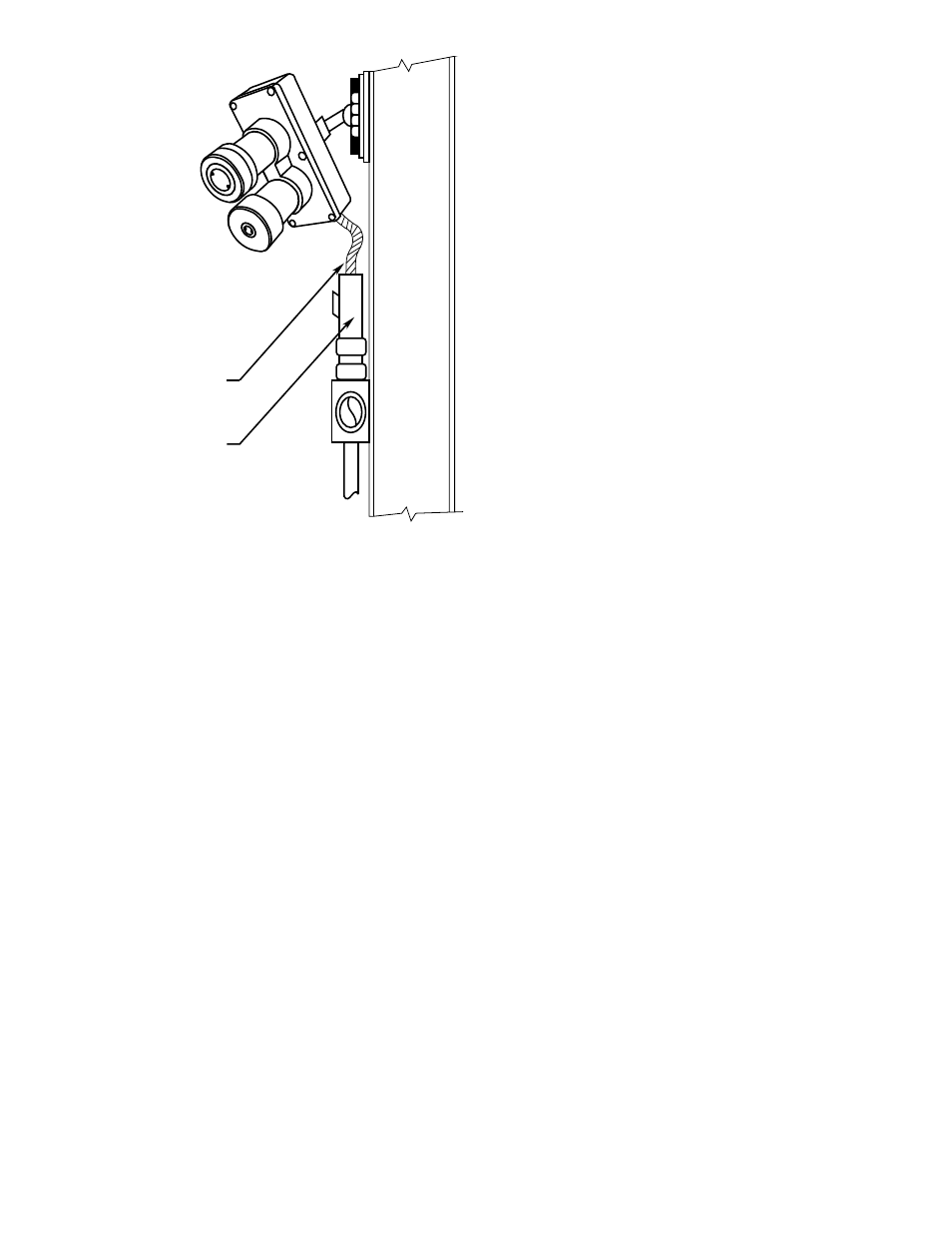
PROVIDE ENOUGH CABLE
FOR ADJUSTMENT OF SWIVEL
CONDUIT SEAL
A1478
Figure 11—Vertical Mountign Detector