Troubleshooting, Device repair and return, Engineering specifications – Det-Tronics C7052J UV/IR Flame Detector used with R7494, R7495 Controller User Manual
Page 23
TROUBLESHOOTING
Table 4 is intended to serve as an aid in locating the
source of a system malfunction. The R7495B Controller is
not designed to be repaired by the customer in the field,
but should be returned to the factory in the event of a mal-
function. Refer to the “Maintenance” section of this man-
ual for information regarding servicing of the detector.
DEVICE REPAIR AND RETURN
Prior to returning devices or components, contact the
nearest local Detector Electronics office so that an RMI
(Return Material Identification) number can be
assigned. A written statement describing the malfunc-
tion must accompany the returned device or component
to expedite finding the cause of the failure, thereby
reducing the time and cost of the repair to the customer.
Return all equipment transportation prepaid to the facto-
ry in Minneapolis.
Detector Electronics Corporation
6901 West 110th Street
Minneapolis, Minnesota 55438 USA
Operator: (952) 941-5665 or (800) 765-FIRE
Customer Service: (952) 946-6491
Fax: (952) 829-8750
Web site: www.detronics.com
E-mail: [email protected]
ENGINEERING SPECIFICATIONS
The UV/IR flame detection system shall have a micro-
processor-based controller that can operate up to 8
detectors and provide relay outputs through the use of a
relay output module. The controller shall be field pro-
grammable for selecting time delay length, sensitivity,
voting output configuration, and latching or non-latching
operation. The system shall operate on 24 vdc. The
UV/IR flame detection system shall be capable of
responding to a 1 foot by 1 foot gasoline fire at a dis-
tance of 50 feet. The detector shall be capable of 1.0
second response time to an intense fire signal. It shall
not respond to radiation generated by arc welding, x
rays, or hot surfaces, but shall be capable of respond-
ing to a fire in their presence. The UV/IR flame detector
shall be in a red, copper-free aluminum enclosure1.
The detector shall be the Det-Tronics model C7052J, no
equal. The controller shall be the Det-Tronics model
R7495B Controller and the that fits in the Det-Tronics
model Q4004 Mounting Rack which is designed to fit
standard 19” racks, no equal.
The UV/IR flame detector shall have one 3/4” NPT
2
entry
for field wiring.
The controller shall have visual annunciation of fire and
fault conditions. The controller shall have eight red
LEDs for individual detector alarm indications, one
green LED for power indication, one yellow LED for fault
indication, one red LED to indicate an alarm, and two
red LEDs for fire zone (voting) output indication.
The signal processing shall require the UV radiation and
the flickering IR radiation to exceed field adjust thresh-
old levels and time delay before signalling an alarm
condition. The detector shall have a 80 degree cone of
vision and be of a modular plug-in design that allows
the UV and IR sensor modules to be easily field
replaced without the use of special tools. All optical
surfaces shall be easy to access for cleaning. No metal
rods shall be allowed in front of the sensor windows.
The UV/IR flame detector shall have optical testing
capabilities on both the UV and IR sensor. Films that
blind the UV sensor or the IR sensor shall cause a fail-
ure of the optical test.
The UV/IR flame detector shall be rated for an operating
temperature range of -40°F to +167°F (–40°C to +75°C)
and a storage temperature of -40°F to +185°F (–40°C to
+85°C). The detector shall operate over a humidity
range of 0 to 95% RH and be able to withstand 100%
condensing humidity for short periods of time. All print-
ed circuit boards shall be coated to provide protection
from the environmental conditions. The UV/IR flame
detector shall meet MIL-STD 810C for vibration and
23
95-8302
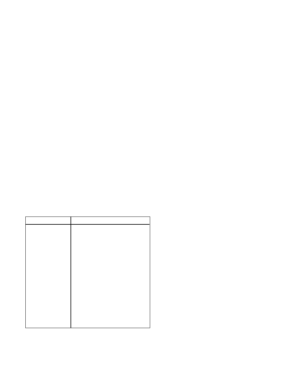
Table 4—Troubleshooting Guide
Problem
Possible Cause
No POWER LED
1. Input power failure.
2. Wiring to external power source
3. Controller power supply failure.
FAULT LED on
1. Mode switch in TEST position.
2. Low input voltage.
FAULT LED and a
1. oi fault - dirty window and/or the
DETECTOR LED on
oi ring
2. Detector module has lost sensitivity
3. Detector wiring problem
FAULT LED off,
1. Detector responding to UV/IR
DETECTOR LED
source not large enough to exceed
blinking slowly
the fire threshold programmed into
the controller
ALARM LED on, no
1. Mode switch in TEST position.
actuation of outputs
2. Output circuit failure.