2 transmission serial number, 4 transmission replacement, 1 transmission removal – Lull 944E-42 Service Manual User Manual
Page 89: Transmission serial number, Transmission replacement, Transmission removal, Warning
6-3
944E-42
Transmission
6.2
TRANSMISSION SERIAL NUMBER
The transmission serial number plate is located on the
pump side (front) of the transmission at the bottom right
toward the machine frame. Information specified on the
serial number plate includes the transmission model
number, the transmission serial number and other data.
Information on the serial number plate is required in
correspondence regarding the transmission.
6.3
TRANSMISSION SPECIFICATIONS
AND MAINTENANCE INFORMATION
For transmission, oil specifications and maintenance
information, refer to Section 2, “General Information and
Specifications.”
Detailed transmission service instructions are provided in
the following publications:
• Service Manual (P/N 31200241)
• Parts Manual (P/N 8990462)
6.4
TRANSMISSION REPLACEMENT
Note: Contact the local distributor if internal
transmission repair is required during the warranty
period.
Note: Cleanliness is of extreme importance. Before
attempting to remove the transmission, thoroughly clean
the exterior of the transmission to help prevent dirt from
entering during the replacement process. Avoid spraying
water or cleaning solution onto or near the transmission
shift solenoids and other electrical components.
6.4.1
Transmission Removal
1. Park the machine on a firm, level surface, level the
machine, fully retract the boom, raise the boom,
place the transmission control lever in (N)
NEUTRAL, engage the park brake and shut the
engine OFF.
2. Place a Do Not Operate Tag on both the ignition key
switch and steering wheel, stating that the machine
should not be operated.
3. Temporarily block up or support the boom.
4. Open the engine cover. Allow the system fluids to cool.
5. Properly disconnect the batteries.
6. Remove the engine cover.
7. Remove the air cleaner assembly and cover the
exposed intake to prevent dirt and debris from
entering the engine.
8. Raise the machine up and place all four wheels on
blocks so there is a minimum of 36 in. (914 mm) of
clearance between the ground and the bottom of the
engine pod.
9. Remove the engine-to- transmission and
transmission-to-axle drive shafts. Refer to Section
5.4.3, “Drive Shaft Removal.”
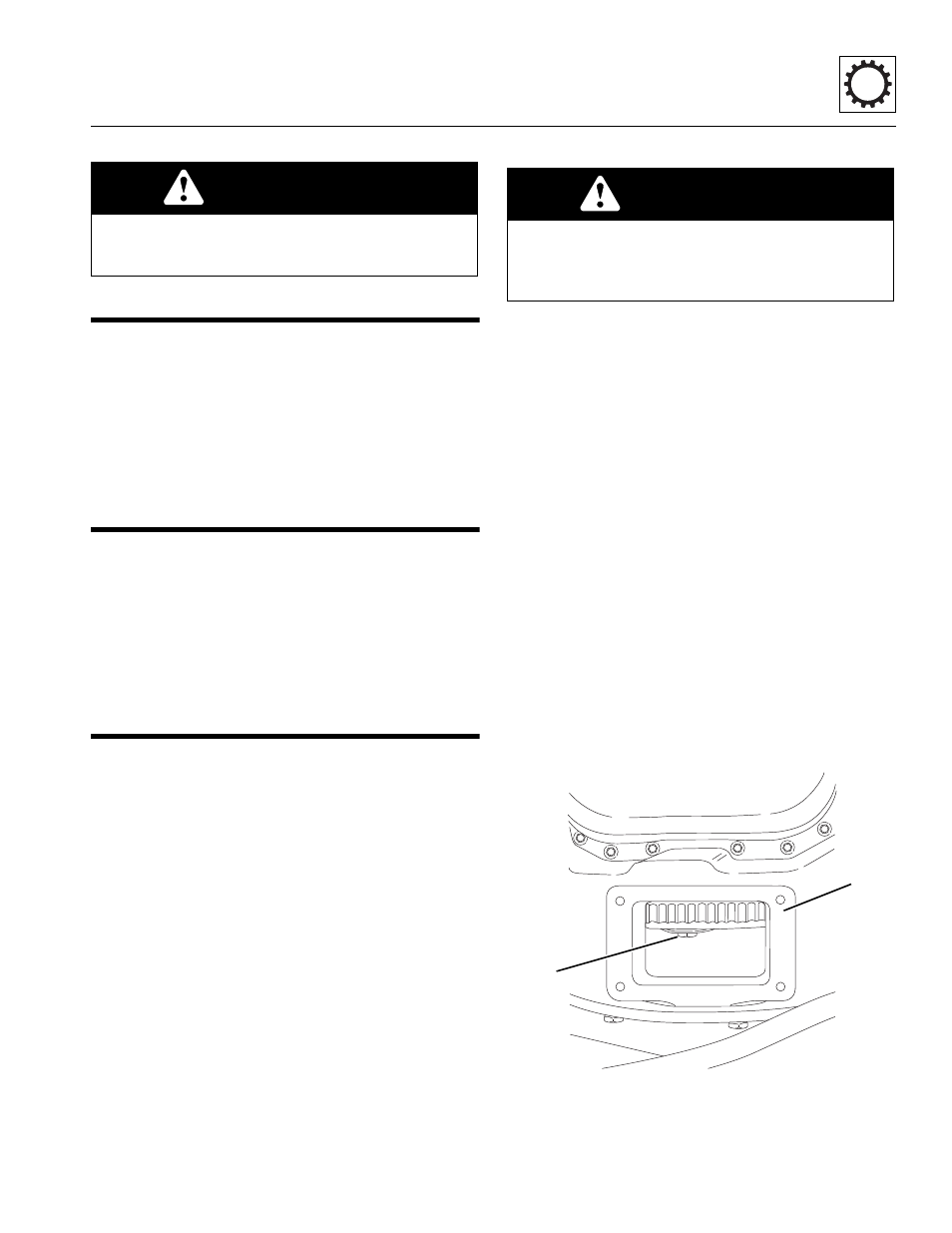
10. Working through the engine flywheel inspection and
access hole (1), remove the four hex head
capscrews (2) securing the converter diaphragm to
WARNING
DO NOT service the machine without following all
safety precautions as outlined in Section 1, “Safety
Practices,” of this manual.
WARNING
NEVER lift a transmission alone; enlist the help of at
least one assistant or use a suitable hoist or overhead
crane and sling with a minimum lifting capacity of
1000 lb (454 kg).
MT1071
2
1