11a 1b, Hydraulic system, Hydraulic pump flow test – Lull 944E-42 Service Manual User Manual
Page 123
8-7
944E-42
Hydraulic System
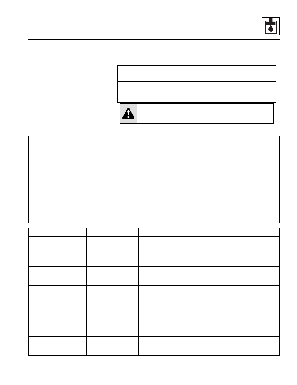
Engine Information
Idle . . . . . . . . . . . . . . . . . . . . . . . . . . 950 rpm
Full Speed . . . . . . . . . . . . . . . . . . . 2500 rpm
Hydraulic Oil Information
Oil Type - 10W, meet ISO Grade 46
Capacity - Reservoir . . . . . . 34 gal. (127 liter)
Capacity - System . . . . . . . 50 gal. (190 liter)
Note: To adjust relief settings, pressure reducing
settings or standby pressure, turn the
adjustment screw clockwise to increase
pressure or counterclockwise to decrease
pressure.
The hydraulic oil temperature for the pump flow
test should be between 100-120° F (38-49° C)
(tank hot to the touch) during testing.
Equipment Needed to Perform Tests
from Hydraulic Diagnostic Test Kit
Test Location
Gauge
Fittings
2, 6, 5
4,000 psi gauge
(280 bar gauge)
Unit equipped with fittings from
factory.
3, 4, 7, 8
1,000 psi gauge
(70 bar gauge)
Unit equipped with fittings from
factory.
9, 10
300 psi gauge
(21 bar gauge)
Requires a #4 o-ring Boss Fitting
with Diagnostic Nipple.
CAUTION: GAUGE DAMAGE may occur. Malfunctioning hydraulic system circuits
may have excessive pressure and can cause hydraulic pressure spikes. Test circuit
with the highest reading pressure gauge first. If this gauge cannot record an
accurate pressure reading, use the next lower pressure gauge.
TEST
SEQUENCE
TEST
LOCATION
Hydraulic Pump Flow Test
1
1a
1b
To check flow readings, a flow meter capable of measuring 60 gpm (227,1 liter/min) and a load valve
capable of 6,000 psi (413,4 bar) will be required (not included with Hydraulic Diagnostic Test Kit).
Test both pump sections of the tandem gear pump separately. Test the primary pump section first. When testing
the pump sections, return the oil from the flow meter directly into the hydraulic tank fill hole.
Run test at 2,000 psi (137,8 bar) load @ Engine Speed of 2,475 - 2,525 rpm.
PRIMARY PUMP (pump section closest to the transmission) - Label and disconnect the outlet hose from the
primary pump and allow the hose to hang loose. Cover, cap or plug the primary pump outlet hose to prevent
contamination of the hydraulic system. Connect the flow meter to the outlet port on the primary pump — Flow rate
should be 16.5-19.5 GPM (62,5-73,8 liter/min).
SECONDARY PUMP (pump section furthest from the transmission) - Label and disconnect the outlet hose
from the secondary pump and connect to the outlet port on the primary pump. Connect the flow meter to the outlet
port on the secondary pump — Flow rate should be 13.2-15.5 GPM (49,9-58,7 liter/min).
Note: When testing on the secondary pump is completed make sure to disconnect the secondary pump outlet hose
from the primary pump outlet port and reconnect it to the secondary pump outlet port. Also make sure to re-connect the
primary pump outlet hose to the primary pump outlet port.
TEST
SEQUENCE
TEST
LOCATION
Valve
Port
ADJUST.
LOCATION
COMPONENT
DESCRIPTION
PRESSURE
READINGS
PRESSURE TEST PROCEDURES
2
10
—
N/A
Stand By
Pressure
275-375 psi
(19,0-25,8 bar)
With engine at idle, check the pressure. The pressure is not
adjustable. If the pressure is incorrect, replace unloader
cartridge (8) on Main Control Valve.
3
3
PPG
A
Pilot Valve
Pressure
500-600 psi
(34,5-41,4 bar)
With engine at idle, check the pressure. If the pressure is
incorrect, adjust or replace the pressure reducing cartridge
located on the accumulator charge/secondary function valve.
4
4
PBG
A
Accumulator
Charge/
Secondary
Function Valve
Park Brake
Release
500-600 psi
(34,5-41,4 bar)
With engine at idle, turn the park brake switch to the disengaged
position. Check the pressure. If the pressure is incorrect, adjust
or replace the pressure reducing cartridge located on the
accumulator charge/secondary function valve.
5
5
P1
B
Power Steering
Supply
2,600-2,800 psi
(179-193 bar)
With engine at idle, turn the steering wheel all the way in one
direction and hold while checking pressure. If pressure is
incorrect, adjust or replace the relief valve located on the
accumulator charge/secondary function valve.
6
6
SW
N/A
Accumulator
Charge/
Secondary
Function Valve
See “Pressure
Test Procedures”
for Pressure
Readings
At start up, the pressure should jump up to and stop
momentarily at 750 psi (51,7 bar), which is the pre-charge
pressure. The pressure should then continue to rise to 2,200-
2,400 psi (151,6-165,4 bar) which is the accumulator charge
pressure. Let the system bleed down naturally with the engine
at idle (minimum of 2 minutes). The accumulator charge
pressure should recharge at 1145-1345 psi (78,9-92,7 bar).
7
2
—
C
Main System
Relief
3,400-3,600 psi
(234-248 bar)
With engine at high idle, use the boom control lever to fully
retract the boom. Hold over relief and check pressure. If
pressure is incorrect, adjust or replace cartridge located in the
end section of the main control valve.