9 service brake valve, Section 8.7.9, “service brake valve,” f, Section 8.7.9, “service brake valve – Lull 944E-42 Service Manual User Manual
Page 144: Service brake valve
Hydraulic System
8-28
944E-42
6. Inspect the release valve for leaks and check the
level of the hydraulic fluid in the reservoir. Shut the
engine OFF.
7. Wipe up any hydraulic fluid spillage in, on, near and
around the machine, work area and tools.
8. Reinstall the access plate to the cab floor.
9. Close and secure the engine cover.
8.7.9
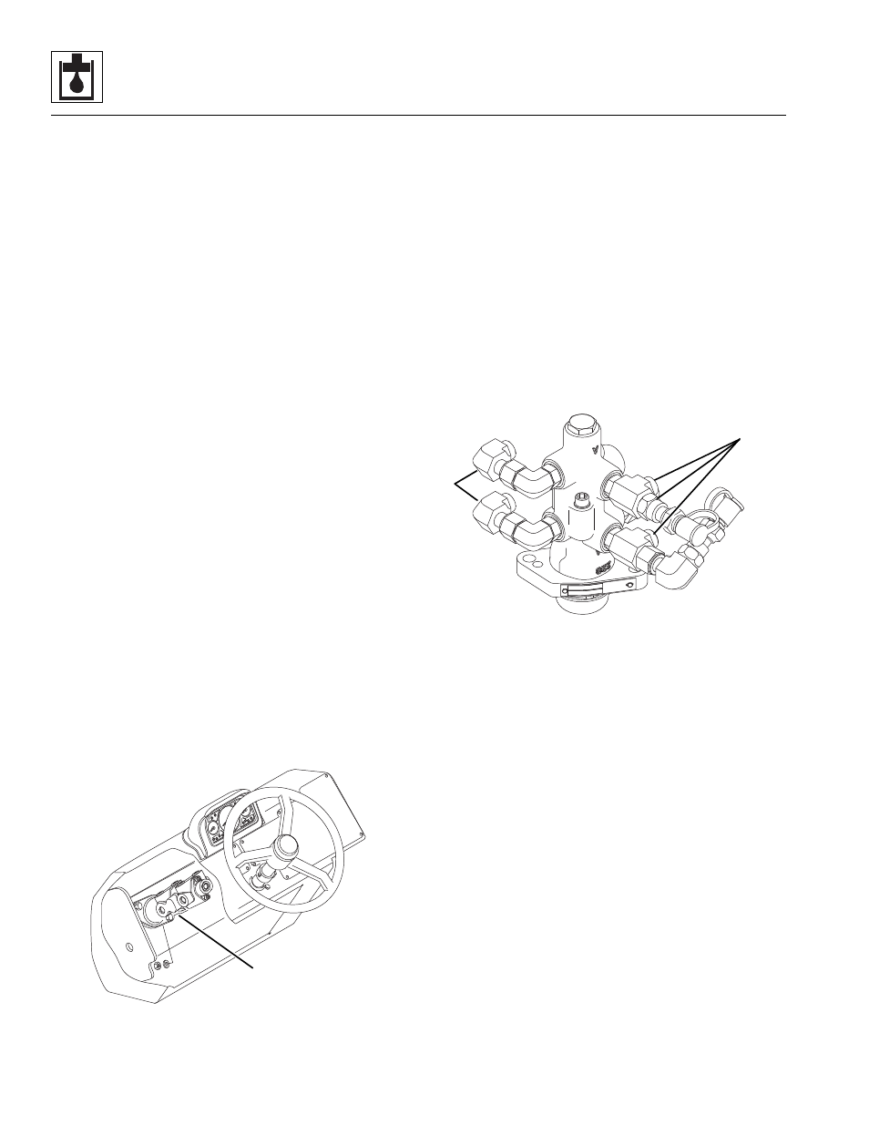
Service Brake Valve
The service brake valve is secured at the base of the
steering column support inside the dash, concealed by
the lower dash cover.
The service brakes themselves are part of the axles (the
park brake is part of the front axle only). Refer to Section
5.3, “Axle Assemblies.”
a. Service Brake Valve Removal
1. Park the machine on a firm, level surface, level the
machine, fully retract the boom, lower the boom,
place the transmission control lever in (N) NEUTRAL,
engage the park brake and shut the engine OFF.
2. Place a Do Not Operate Tag on both the ignition key
switch and the steering wheel, stating that the
machine should not be operated.
3. Open the engine cover. Allow the system fluids to
cool.
4. Properly disconnect the batteries.
5. Remove the lower dash panel.
6. Pump the brake pedal several times to relieve all the
stored pressure in the accumulator system.
7. Remove the brake pedal from the dash. Refer to
Section 4.3.3, “Service Brake Valve and Pedal,” for
the proper removal procedure.
8. Label, disconnect and cap all hoses attached to the
service brake valve (3).
9. Remove the two capscrews, washers and nuts
mounting the service brake valve to the steering
column support. Remove the service brake valve
through the lower dash panel opening.
b. Service Brake Valve Installation
Note: DO NOT disassemble the service brake valve.
The service brake valve is not serviceable and must be
replaced in its entirety, if defective.
Note: ALWAYS replace seals, o-rings, gaskets, etc.,
with new parts to help ensure proper sealing and
operation. Lubricate seals and o-rings with clean
hydraulic oil.
1. Transfer the fittings (4) to the new brake valve. Note
the orientation of each fitting before removing them.
2. Install the service brake valve with the two
capscrews, washers and nuts onto the steering
column support.
3. Use new oiled o-rings as required. Uncap and
connect the previously labeled hoses to the service
brake valve.
4. Check the routing of all hoses, and tubing for sharp
bends or interference with any rotating members,
and install tie wraps and/or protective conduit as
required. Tighten all tube and hose clamps.
5. Properly connect the batteries.
6. Start the engine and run at approximately one-third
to one-half throttle for about one minute, without
moving the machine or operating any hydraulic
functions.
7. Inspect the service brake valve and connections for
leaks, and check the level of the hydraulic fluid in the
reservoir. Shut the engine OFF.
MU3412
3
MU3501
4
4