4 hydraulic circuits, 1 hydraulic pressures, Hydraulic circuits – Lull 944E-42 Service Manual User Manual
Page 121: Section 8.4, “hydraulic, Circuits, Hydraulic pressures, Caution
8-5
944E-42
Hydraulic System
7. Check the pressure gauge reading. It should read as
specified in the Pressure Readings column of the
charts found in Section 8.4.1, “Hydraulic Pressures.”
If the reading is not as specified, turn the engine
OFF and check other components in the system.
Verify that all related hydraulic components and
electrical switches, sensors, solenoids, etc. are
operating correctly.
8. Adjust the relief valve by turning the adjustment
screw Turning clockwise will increase the pressure;
turning the screw counterclockwise will decrease the
pressure.
9. Start the engine and check the pressure again. Turn
the engine OFF. If there is pressure reading in the
gauge, bleed it off then disconnect or remove the
pressure gauge from the machine.
8.4
HYDRAULIC CIRCUITS
This section covers the hydraulic circuits and includes
listings for all hydraulic function pressures, where and
how to check those pressures and a hydraulic schematic.
Electrical and hydraulic functions are often related. Verify
that the electrical components of the circuit are
functioning properly whenever troubleshooting the
hydraulic circuit.
Always check the following before beginning to
troubleshoot a circuit that is not functioning correctly.
1. Check the hydraulic oil level in the reservoir. Oil level
should be to the middle of the sight glass with all
cylinders retracted.
2. Check hoses, tubes, fittings and other hydraulic
components for leaks, bends, kinks, interference, etc.
3. Check for air in the hydraulic system. Erratic machine
performance and/or spongy cylinder operation are
signs of air in the hydraulic system.
If air in the hydraulic system is suspected, you will
hear air leakage when hydraulic fittings are loosened
and see air bubbles in the hydraulic fluid.
Loose fittings, faulty o-rings or seals, trapped oil,
leaks, system opened for service, etc., can cause air
in the system. Determine what is causing air to enter
the system and correct it. Bleed air from the system.
8.4.1
Hydraulic Pressures
a. Checking Pressure
1. Start the machine and warm the hydraulic system to
operating temperature.
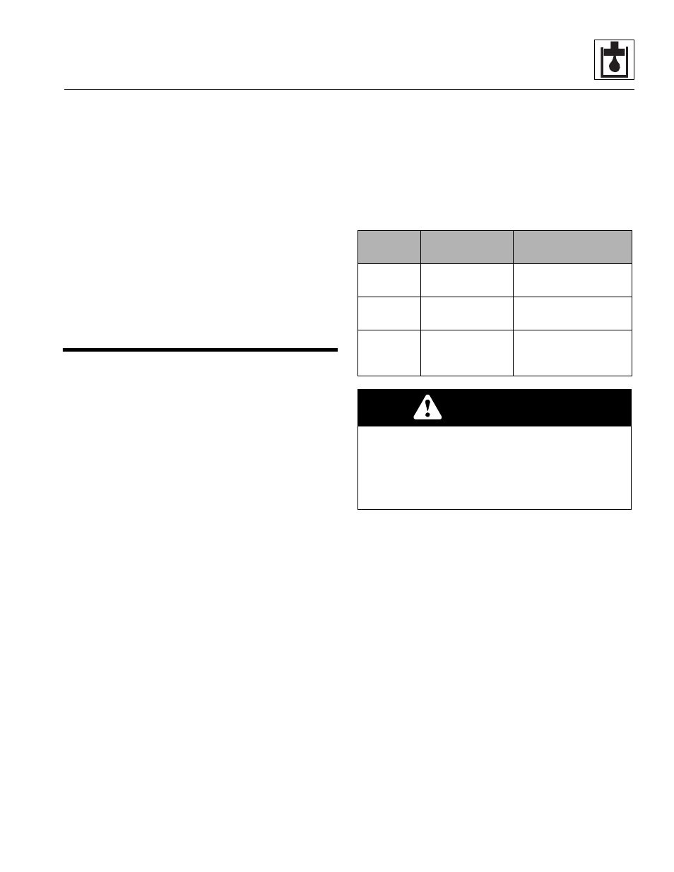
2. Shut off the machine and install a gauge of suitable
pressure rating according to the following chart to
the appropriate test port.
3. Start the machine, run the engine and follow the
procedures in Section 8.4.1, c. “Hydraulic Testing -
Dual Joysticks.”
b. Adjusting Hydraulic Pressure
1. Shut the machine off. Remove the cap on the relief
(if necessary).
2. Start the machine and loosen the jam nut on the
relief. Turn the relief clockwise to increase pressure
or counter-clockwise to decrease pressure. Set to
the correct pressure.
3. Tighten the jam nut and recheck the pressure at full
throttle. If the reading is within specification, shut the
machine off, install the safety cap and remove the
gauge from the test port.
4. If the proper pressure cannot be set, use the
accompanying hydraulic schematic and/or the
electrical schematic to help troubleshoot and correct
the problem.
Test
Location
Gauge
Fittings
2, 3, 4, 5
4000 psi gauge
(280 bar gauge)
Unit equipped with
fittings from factory.
6, 7, 8, 10
1000 psi gauge
(70 bar gauge)
Unit equipped with
fittings from factory.
9
4000 psi gauge
(280 bar gauge)
Requires a male or
female quick
disconnect coupler.
CAUTION
GAUGE DAMAGE may occur. Malfunctioning
hydraulic system circuits may have excessive
pressure and can cause hydraulic pressure spikes.
Test circuit with the highest reading pressure gauge
first. If this gauge cannot record an accurate pressure
reading, use the next lower pressure gauge.