5 joystick valve (single joystick), Joystick valve (single joystick) – Lull 944E-42 Service Manual User Manual
Page 140
Hydraulic System
8-24
944E-42
4. Start the machine and run at approximately one-third
to one-half throttle for about one minute without
moving the machine or operating any hydraulic
function.
5. Inspect the pilot select valve for leaks and check the
level of the hydraulic fluid in the reservoir. Shut the
engine OFF.
6. Wipe up any hydraulic fluid spillage in, on, near and
around the machine, work area and tools.
7. Reinstall the access plate to the cab floor.
8. Close and secure the engine cover.
a. Pilot Select Valve Test
Conduct a pressure check of the joystick circuit. Refer to
Section 8.3.1, “Pressure Checks and Adjustments.”
8.7.5
Joystick Valve (Single Joystick)
Pilot pressure from the joystick flows to the single joystick
pilot select valve (3). Joystick commands are actuated
both electrically and hydraulically via a set of solenoid-
operated control valves mounted in an array at the pilot
select manifold.
Verify the correct operation of the joystick switches and
circuit solenoids before considering replacement of the
joystick valve. Refer to Section 9.5.2, “944E-42 Electrical
Schematics.”
The valve itself is not serviceable and must be replaced
in it’s entirety if replacement of electrical parts does not
solve the problem. Refer to Section 9.5.2, “944E-42
Electrical Schematics.”
After replacing the joystick valve assembly, check all
joystick functions.
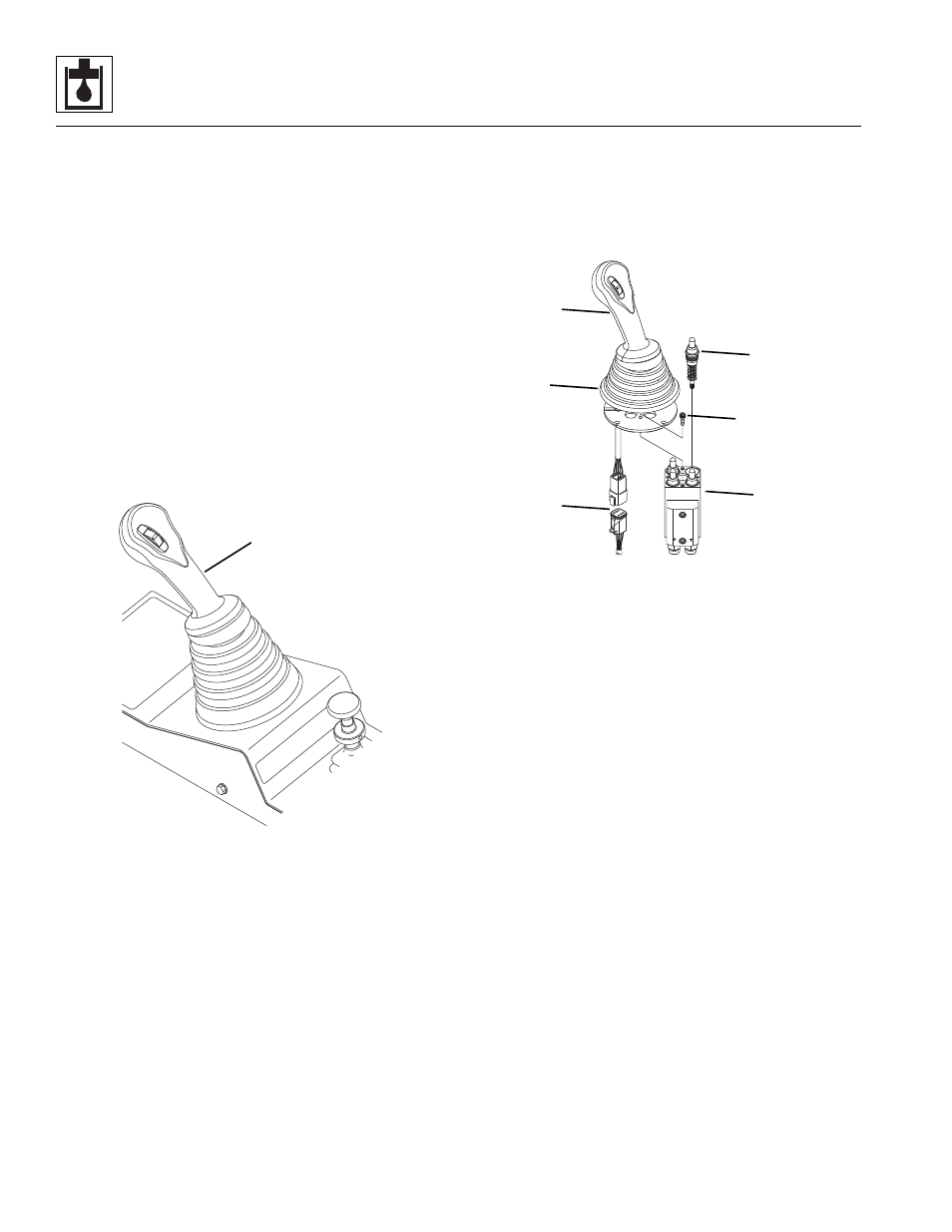
a. Single Joystick Capsule Replacement
1. Remove the entire single joystick assembly from the
cab. Refer to Section 4.3.6, “Joystick Assemblies.”
2. Secure the single joystick body in s vise or suitable
device.
3. Disconnect the joystick harness connection (4).
4. Lift up the boot (5), loosen and remove the
capscrews (6) that secure the joint and handle
assembly (7) to the valve body (8). Lift the joint and
handle assembly from the top of the valve body.
5. Remove the capsules (9) from the valve body.
6. Clean all components with a suitable cleaner before
inspection.
7. Inspect internal passageways of the pilot select
valve and it’s component parts for wear, damage,
etc. If inner surfaces of the pilot select valve DO NOT
display an ultra-smooth, polished finish, or
components are damaged in any way, replace the
pilot select valve or appropriate part. Often, dirty
hydraulic fluid causes failure of internal seals and
damage to the polished surfaces within the pilot
select valve.
8. Assemble the new capsule assembly (9), with the
lightly oiled o-ring, into the valve body (8).
9. Reassemble the joint and handle assembly (7) to the
valve body (8). Torque the four capscrews (6) to
7 ± 1 lb-ft (9,5 ± 1,4 Nm).
10. Reassemble the boot to the joint and handle
assembly.
11. Reconnect the joystick harness connection.
12. Replace the joystick body into the cab. Refer to
Section 4.3.6, “Joystick Assemblies.”
MU6301
3
MU6321
4
6
5
7
8
9